Fluid separation method and fluid separation apparatus

Inactive Publication Date: 2010-12-09
NAT TAIWAN UNIV OF SCI & TECH
View PDF5 Cites 5 Cited by
  • Summary
  • Abstract
  • Description
  • Claims
  • Application Information

AI Technical Summary

Benefits of technology

[0009]Accordingly, the present invention is directed to a fluid separation method,

Problems solved by technology

In addition, with the rapid development of the industry, various gases are mixed together and cannot be completely separated and analyzed respectively In this manner, the gases not only encounter a bottleneck in waste disposal, but the gases are also hard to be analyzed if they cannot be efficiently separated, which thus result in burdens of a manufacturing cost and a waste disposal cost.
Furthermore, components of the mixed fluid cannot be analyzed, which also causes potential risks.
However, the separation column two in the prior art canno

Method used


Image

  • Fluid separation method and fluid separation apparatus
  • Fluid separation method and fluid separation apparatus
  • Fluid separation method and fluid separation apparatus

Examples


first embodiment

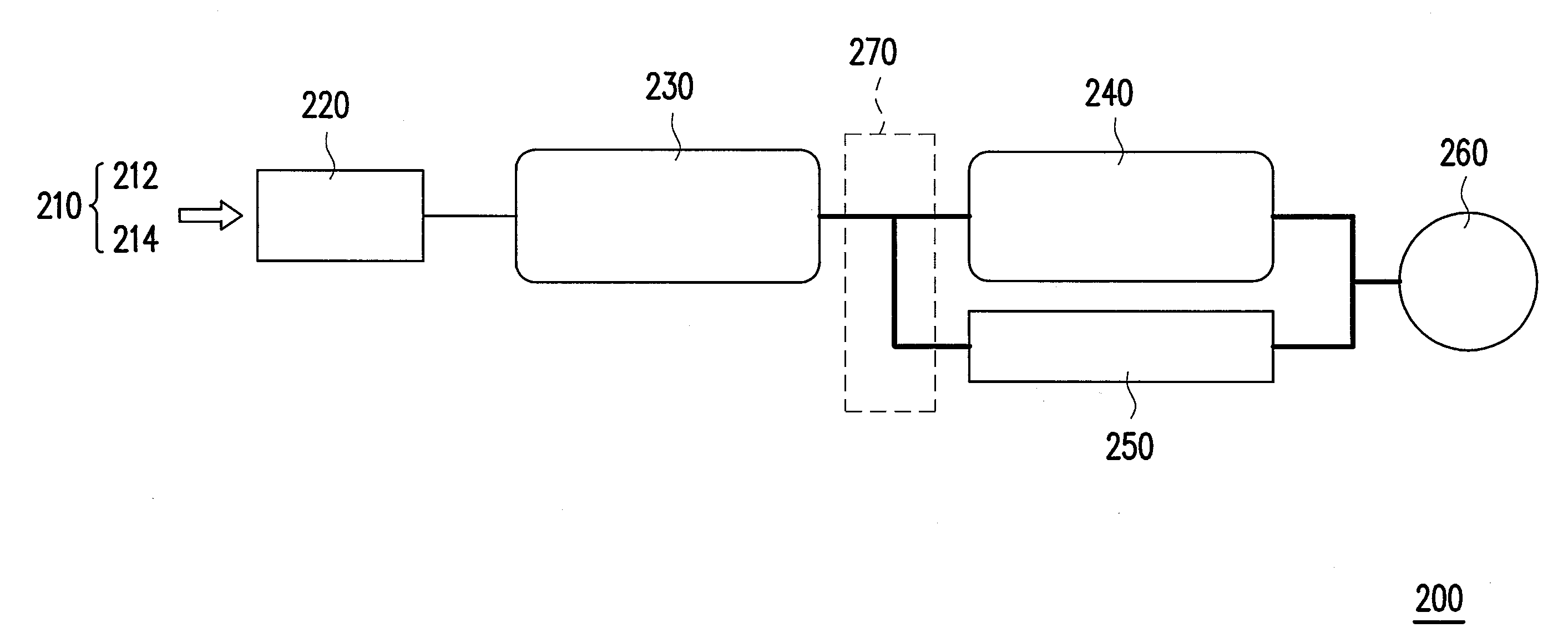
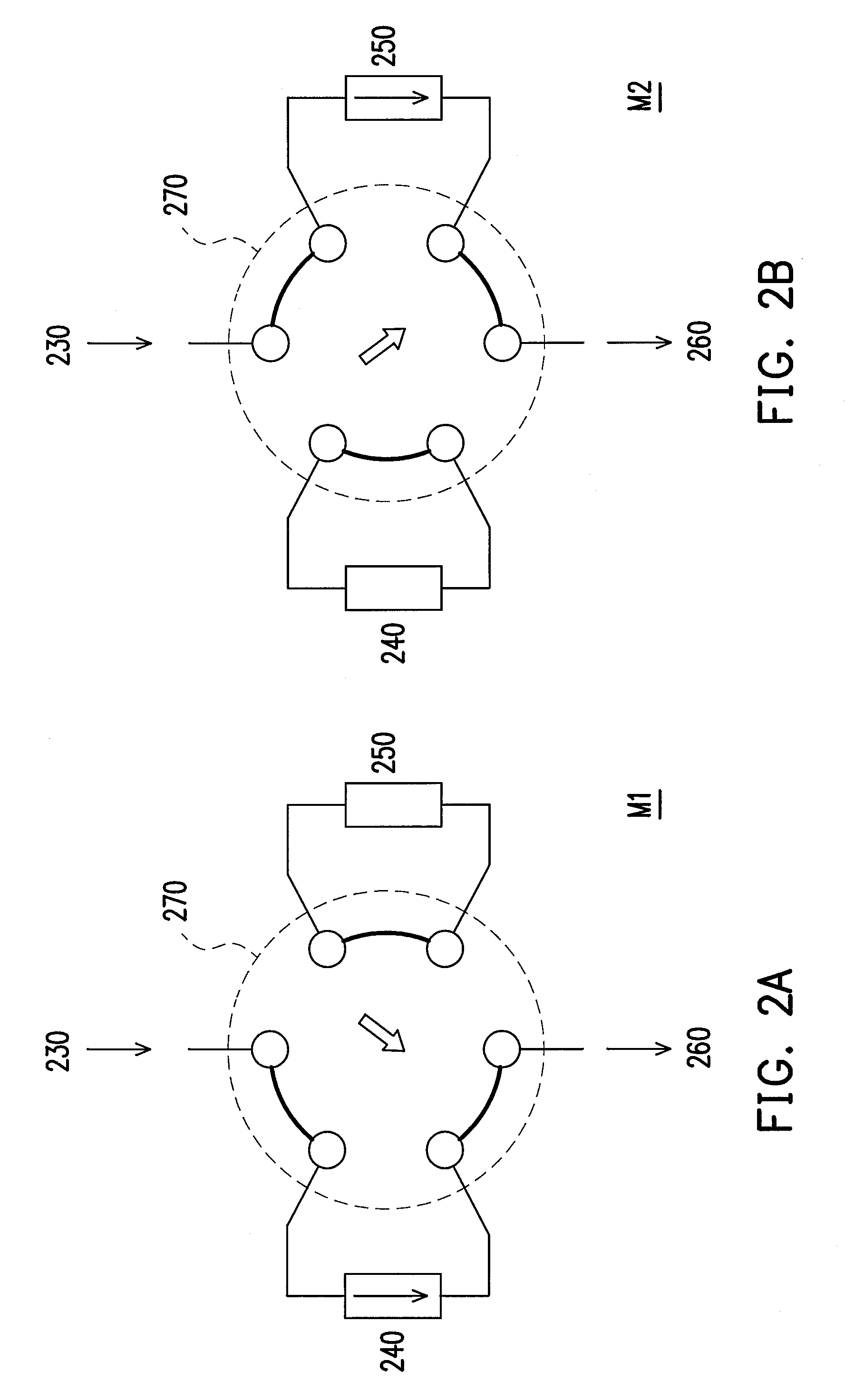
[0042]FIG. 1 is a schematic view of a fluid separation apparatus according to an embodiment of the present invention. A fluid separation apparatus 200 is suitable for separating a mixed fluid 210 with different properties, in which the properties refer to physical properties herein. Definitely, the mixed fluid 210 may be a mixed gas or a mixed liquid, which is not limited in the present invention. The mixed fluid 210 at least includes a first fluid 212 and a second fluid 214. In this embodiment, the first fluid 212 and the second fluid 214 are a non-polar fluid and a polar fluid respectively. Referring to FIG. 1, the fluid separation apparatus 200 mainly includes a sampling entrance 220, a first separation column 230, a second separation column 240, a bypass line 250, a detector 260, and a guide multi-channel valve 270. In particular, the first separation column and the second separation column may employ chromatography columns.

[0043]Referring to FIG. 1, a mixed fluid flows into the...

second embodiment

[0053]In order to make the technical content of the present invention more comprehensible, a fluid separation method according to a second embodiment of the present invention is described below with reference to FIGS. 7A to 7C, in which a gas including H2, CO2, and H2O is, for example, used as a mixed fluid 210 to be separated.

[0054]FIGS. 7A to 7C show a processing flow of a fluid separation method according to a second embodiment of the present invention. Referring to FIG. 7A, first, a mixed fluid 210 with different properties is provided, and the mixed fluid 210 includes components of H2, CO2, and H2O, in which the mixed fluid 210 at least includes a first fluid CO2 and H2O belonging to a polar fluid and a second fluid H2 belonging to a non-polar fluid. Next, the mixed fluid H2, CO2, and H2O is delivered to a first separation column 230 via a sampling entrance 220, and the process of providing the mixed fluid 210 to the first separation column 230 via the sampling entrance 220 can...

third embodiment

[0059]In order to make the technical content of the present invention more comprehensible, a fluid separation method according to a third embodiment of the present invention is described below with reference to FIGS. 9A to 9D, in which a gas of a group consisting of H2, O2, N2, CH4, CO, CO2, H2O, CH3OH, and C2H5OH is, for example, used as a mixed fluid 210 to be separated.

[0060]FIGS. 9A to 9D show a processing flow of a fluid separation method according to a third embodiment of the present invention. For ease of description, in this embodiment, those parts in this embodiment similar to the processing flow as shown in FIGS. 7A to 7C are not described.

[0061]Briefly, in the flow of FIG. 9A, a sampling multi-channel valve 290 is switched from a preset sampling mode M3 to a sample inlet mode M4, such that the mixed fluid H2, O2, N2, CH4, CO, CO2, H2O, CH3OH, and C2H5OH including both the polar gas and the non-polar gas is delivered to a first separation column 230 via a sampling entrance...


PUM


Abstract

A fluid separation apparatus suitable for separating a mixed fluid with different properties and capable of separating a complex fluid mixture efficiently is provided. The fluid separation apparatus includes a sampling entrance, a first separation column, a second separation column, a bypass line, a detector and a guide multi-channel valve. A mixed fluid flows into the first separation column via the sampling entrance. The second separation column is connected to the first separation column in series and connected to the bypass line in parallel. The detector is connected to the second separation column and the bypass line. The guide multi-channel valve has different modes to control a flow-through status and a closed status between the first separation column and the second separation column, between the first separation column and the bypass line, between the second separation column and the detector, and between the bypass line and the detector.

Description

CROSS-REFERENCE TO RELATED APPLICATION[0001]This application claims the priority benefit of Taiwan application serial no. 98119234, filed Jun. 9, 2009. The entirety of the above-mentioned patent application is hereby incorporated by reference herein and made a part of specification.BACKGROUND OF THE INVENTION[0002]1. Field of the Invention[0003]The present invention generally relates to a fluid separation method and a fluid separation apparatus, in particular, to a fluid separation method and a fluid separation apparatus capable of highly efficiently separating a complex fluid mixture.[0004]2. Description of Related Art[0005]In the past, during the manufacturing process of semiconductor integrated circuits, liquid crystal panels, solar cell panels, and magnetic devices etc., various different gases or liquids are usually used according to product types and manufacturing flows. For example, in a dry etching step or thin film forming step, various gases, for example, CF4, NF3, C3F8, S...

Claims


Application Information

Patent Timeline
IPC IPC(8): B01D53/02
CPCB01D53/0423B01D53/0454G01N2030/207G01N30/468G01N30/461
Inventor YANG, SHENG-CHIANGLU, SHIH-CHIHWANG, BING-JOE
Owner NAT TAIWAN UNIV OF SCI & TECH
Why Eureka
Try Eureka