Disc transfer mechanism and disc drive apparatus

Active Publication Date: 2012-01-26
JVC KENWOOD CORP A CORP OF JAPAN
View PDF9 Cites 6 Cited by
  • Summary
  • Abstract
  • Description
  • Claims
  • Application Information

AI Technical Summary

Benefits of technology

[0011]The invention has been accomplished in view of the foregoing circumstances, and it is an object of the invention to provide a disc transfer mechanism with a simple structure and a small parts count so that a disc can be transferred appropriately, and to enable the drive unit to be secured and supported by utilizing the disc transfer mechanism when, for example, transferring a disc.
[0024]According to the invention, the drive cam and the driven cam are engaged with both ends of the feed roller . Therefore, even when the number of the springs for pressing the feed roller against the disc to be transferred is reduced or when the spring force of the springs is weakened, the feed roller can be retained at the position to be pressed against the disc by the drive cam and the driven cam. As a result, the disc can be transferred appropriately while the feed roller is kept pressed against the disc.
[0026]In addition, according to embodiments, the drive cam and the driven cam are engaged with the respective ends of the feed roller so that the driven cam can move rectilinearly in cooperation with pivoting of the feed roller by the drive cam. As a result, no dedicated part is needed for the linked movement of the drive cam and the driven cam and the manufacturing cost can be suppressed by employing the simple structure.
[0028]In addition, since the drive unit is elastically supported by an anti-vibration damper, recording and reproducing of information can be performed appropriately even under a vibration environment. Furthermore, each of the drive cam and the driven cam has a unit-securing-and-supporting portion for restraining an edge portion of the drive unit when the feed roller is at the disc transfer position. Therefore, the disc loaded by the feed roller in the apparatus main body can be arranged appropriately for the drive unit in a restrained state.

Problems solved by technology

Consequently, a problem arises that the disc cannot be transferred appropriately.
However, when the disc is transferred and the drive unit is kept in an elastically supported condition, the relative position between the drive unit and the disc transfer mechanism is not fixed so it is possible that the disc may not be guided onto the turntable of the drive unit.
However, since the member is provided only on one side of the drive unit, it is impossible to secure and support the drive unit appropriately only by the member.
Consequently, parts count and the assembling man-hour for the apparatus as a whole increase, resulting in a cost increase.

Method used


Image

  • Disc transfer mechanism and disc drive apparatus
  • Disc transfer mechanism and disc drive apparatus
  • Disc transfer mechanism and disc drive apparatus

Examples


Embodiment Construction

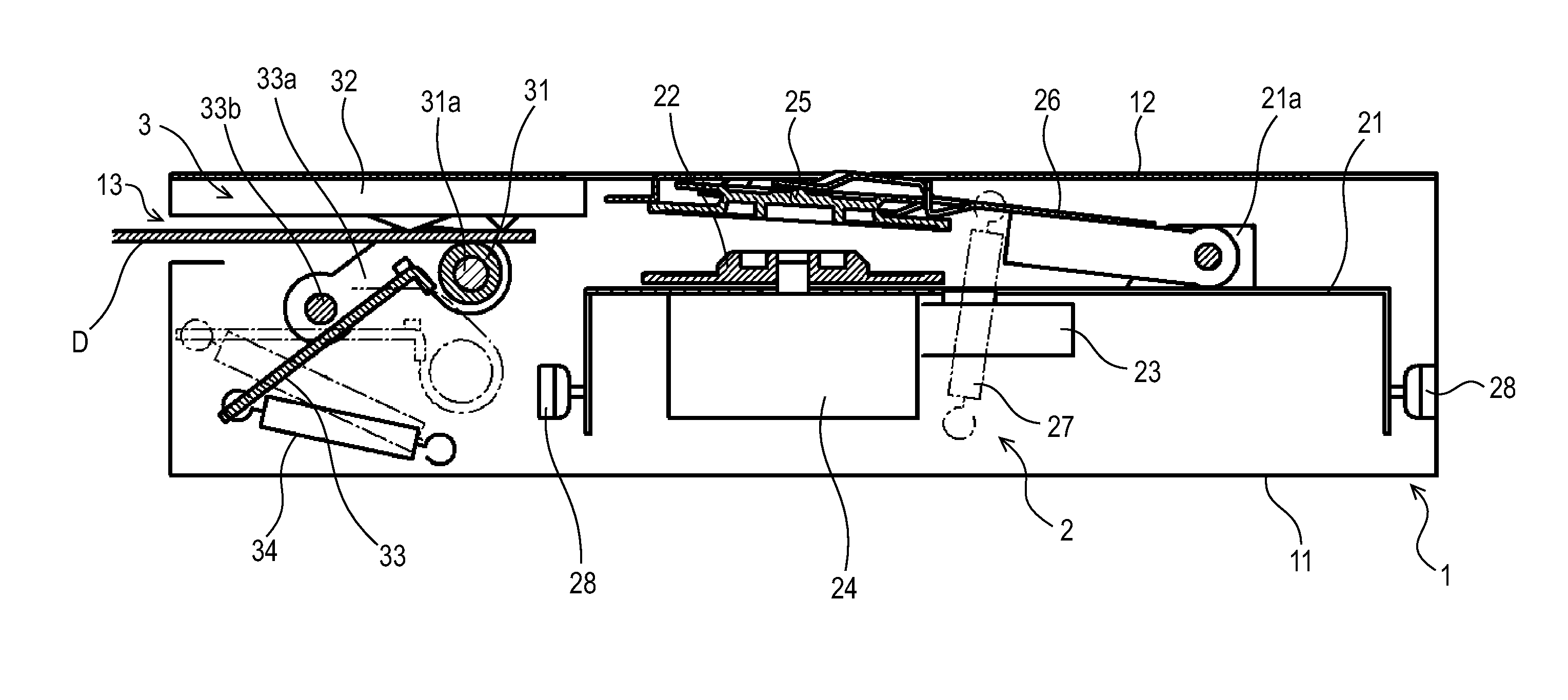
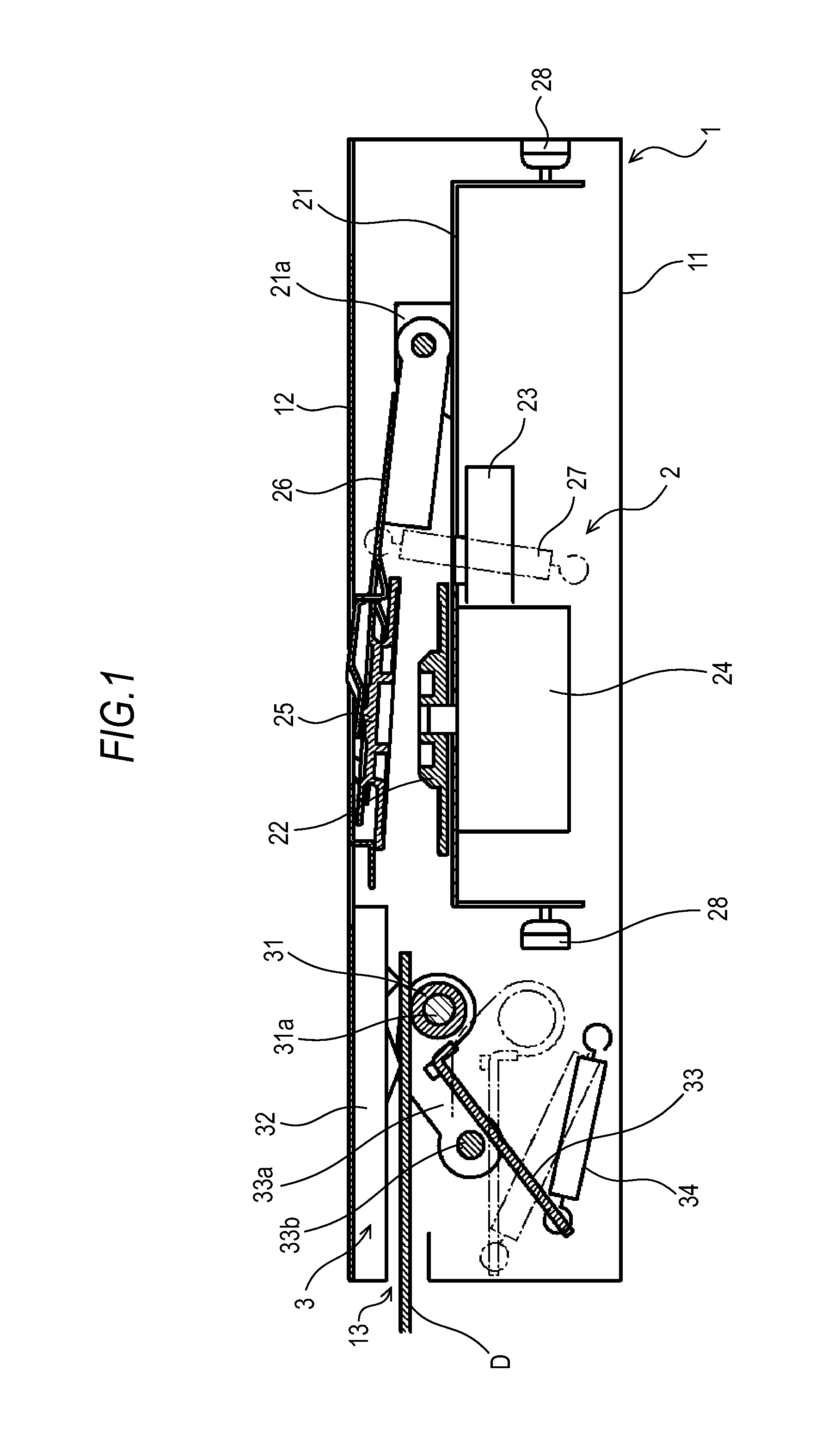
[0049]Hereinbelow, embodiments will be described in detail with drawings. First, in FIG. 1, reference numeral 1 denotes a case (apparatus main body) that forms the exterior of the apparatus. The case 1 has a base chassis 11 formed by press-molding a metal plate and a top plate 12 for covering the upper portion of the base chassis 11. A horizontal insert slot 13 for loading and ejecting a disc D is formed on the front face of the case 1.

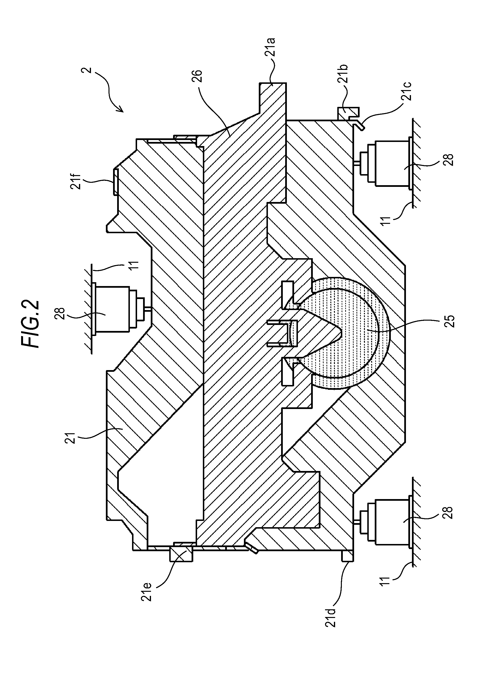
[0050]Reference numeral 2 denotes a drive unit, which is commonly referred to as a transfer mechanism. This drive unit 2 is constructed by integrally fitting a turntable 22, an optical pickup 23, and so forth to a seat plate 21 made of a metal. The turntable 22 is a circular-shaped rotation member for supporting and rotating the disc D. The turntable 22 is directly coupled to a rotor shaft of a spindle motor 24 fixed to the seat plate 21 and is rotated in one direction. The optical pickup 23 is an electronic component unit for reading recorded informa...


PUM


Abstract

A disc transfer mechanism includes a feed roller provided between a drive unit incorporated in a drive apparatus main body and an insert slot formed in the apparatus main body; a roller supporting member pivotably supporting the feed roller between a disc transfer position and an evacuated position; a drive cam for pivoting the feed roller between the disc transfer position and the evacuated position; and a driven cam moving in cooperation with pivoting of the feed roller. The drive cam engages with a rotation shaft of the feed roller and moves rectilinearly along one peripheral end of the drive unit, and the driven cam moves rectilinearly along the other peripheral end of the drive unit.

Description

CROSS REFERENCE TO RELATED APPLICATIONS[0001]This application claims priority based on 35 USC 119 from prior Japanese Patent Application No. P2010-163468 filed on Jul. 21, 2010, entitled “DISC TRANSFER MECHANISM AND DISC DRIVE APPARATUS”, the entire contents of which are incorporated herein by reference.BACKGROUND OF THE INVENTION[0002]1. FIELD OF THE INVENTION[0003]The present invention relates to a disc drive apparatus used for reproducing music information, for example, recorded in a disc (disc-shaped information recording medium) and recording desired information in a disc. More particularly, the invention relates to a disc transfer mechanism incorporated in an apparatus for transferring the disc, and a disc drive apparatus including the mechanism.[0004]2. DESCRIPTION OF RELATED ART[0005]A conventionally known disc drive apparatus for recording desired information in a disc and reproducing the recorded information is one in which a disc inserted into an insert slot is transferre...

Claims


Application Information

Patent Timeline
IPC IPC(8): B65G13/02G11B17/04
CPCG11B17/0404G11B33/08G11B17/051
Inventor OGAWA, MOTOHARU
Owner JVC KENWOOD CORP A CORP OF JAPAN
Why Eureka
Try Eureka