Roller blind assembly

A technology of rolling shutters and rolling springs, applied in door/window protection devices, winding strips, transportation and packaging, etc., can solve the problem of not preventing the torsion spring from fluttering, and achieve the effect of simple buffer profiles

Inactive Publication Date: 2008-04-02
BOS
View PDF1 Cites 6 Cited by
  • Summary
  • Abstract
  • Description
  • Claims
  • Application Information

AI Technical Summary

Problems solved by technology

[0003] Seen as a disadvantage on the roller shutter device, although the device dampens the sound, it does not prevent the vibration of the torsion spring towards the roller shutter wall or towards the shaft

Method used


Image

  • Roller blind assembly
  • Roller blind assembly
  • Roller blind assembly

Examples


Embodiment Construction

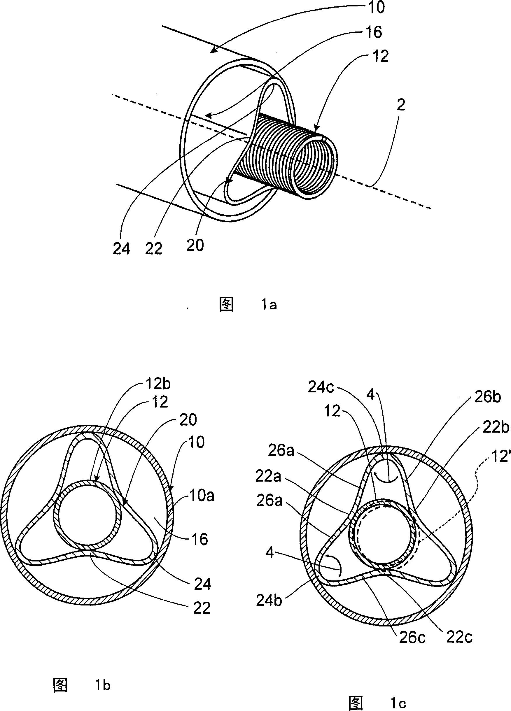
[0036] The illustrated embodiments of the roller blind arrangement according to the invention each only show the roller shaft with the coil spring, the damping element and partly with the spring rod. The remaining components of the roller blind arrangement, such as the flexible flat object or the surrounding housing, are not shown for the sake of clarity.

[0037] FIG. 1 a shows the basic configuration of an example of a first embodiment of a roller shaft of a roller blind arrangement according to the invention: a coil spring 12 is arranged inside the roller shaft 10 , wherein the roller shaft 10 and the coil spring 12 have a common main direction of extension 2 . Inserted in the annular cavity 16 between the reel 10 and the inner coil spring 12 is a damping profile 20 which bears against the coil spring and the reel 10 with an inner contact section 22 and an outer contact section 24 without play.

[0038] FIG. 1 b shows a sectional side view of the reel 10 shown in FIG. 1 a ...


PUM


Abstract

The invention relates to a roller blind arrangement, in particular for use in a vehicle, with a winding shaft ( 10 ) which extends in a main direction of extent ( 2 ), is in the form of a hollow tube and is intended for receiving an unwindable flexible sheetlike structure, a winding spring ( 12 ) which is inserted into the winding shaft ( 10 ), is designed as a helical spring and extends in the main direction of extent, and a damping profile ( 20 ) which extends in the main direction of extent ( 2 ) and is arranged in an annular space ( 16 ) between the winding shaft ( 10 ) and the winding spring ( 12 ). According to the invention, the damping profile ( 20 ) is designed in such a manner that it bears with outer contact sections ( 24 ) against an inner side of the winding shaft ( 10 ) and with inner contact sections ( 22 ) against an outer side of the winding spring ( 12 ). Use, in particular roller blind arrangements in vehicles, for example for coverings of the boot.

Description

technical field [0001] The invention relates to a roller blind device, in particular provided for use in motor vehicles, which has a hollow tubular reel extending in the main direction of extension for accommodating a pullable, flexible planar article, inserting the reel and constructing A coil spring extending in the main direction of extension in the form of a helical spring and a damping profile extending in the main direction of extension, which is arranged in the annular space between the winding shaft and the coil spring. In this case, the invention also relates in particular to a roller blind arrangement in which a spring rod extending in the main direction of extension is inserted into a coil spring. Background technique [0002] Such a roller blind device is known from DE 2941711C2. In the known roller blind device, a tube is arranged between the torsion spring and the outer roller or the inner shaft, which tube rests against the inner or outer side of the torsion ...

Claims


Application Information

Patent Timeline
Patent Type & Authority Applications(China)
IPC IPC(8): B65H18/08B60R13/00B60R5/00B60J1/20B60J7/08B60J11/02B60P7/02E06B9/08
CPCE06B9/44B60J1/2033B60J1/205E06B9/60
Inventor A·吉恩格尔D·鲍尔斯
Owner BOS
Why Eureka
Try Eureka