
Internal combustion engines
a combustion engine and combustion chamber technology, applied in the direction of machines/engines, mechanical equipment, non-fuel substance addition to fuel, etc., can solve the problems of engine efficiency, particularly poor economic condition of gasoline and diesel fuel, etc., to save fuel, save fuel, and save fuel. operation
- Summary
- Abstract
- Description
- Claims
- Application Information
AI Technical Summary
Benefits of technology
Problems solved by technology
Method used
Image

Examples
Embodiment Construction
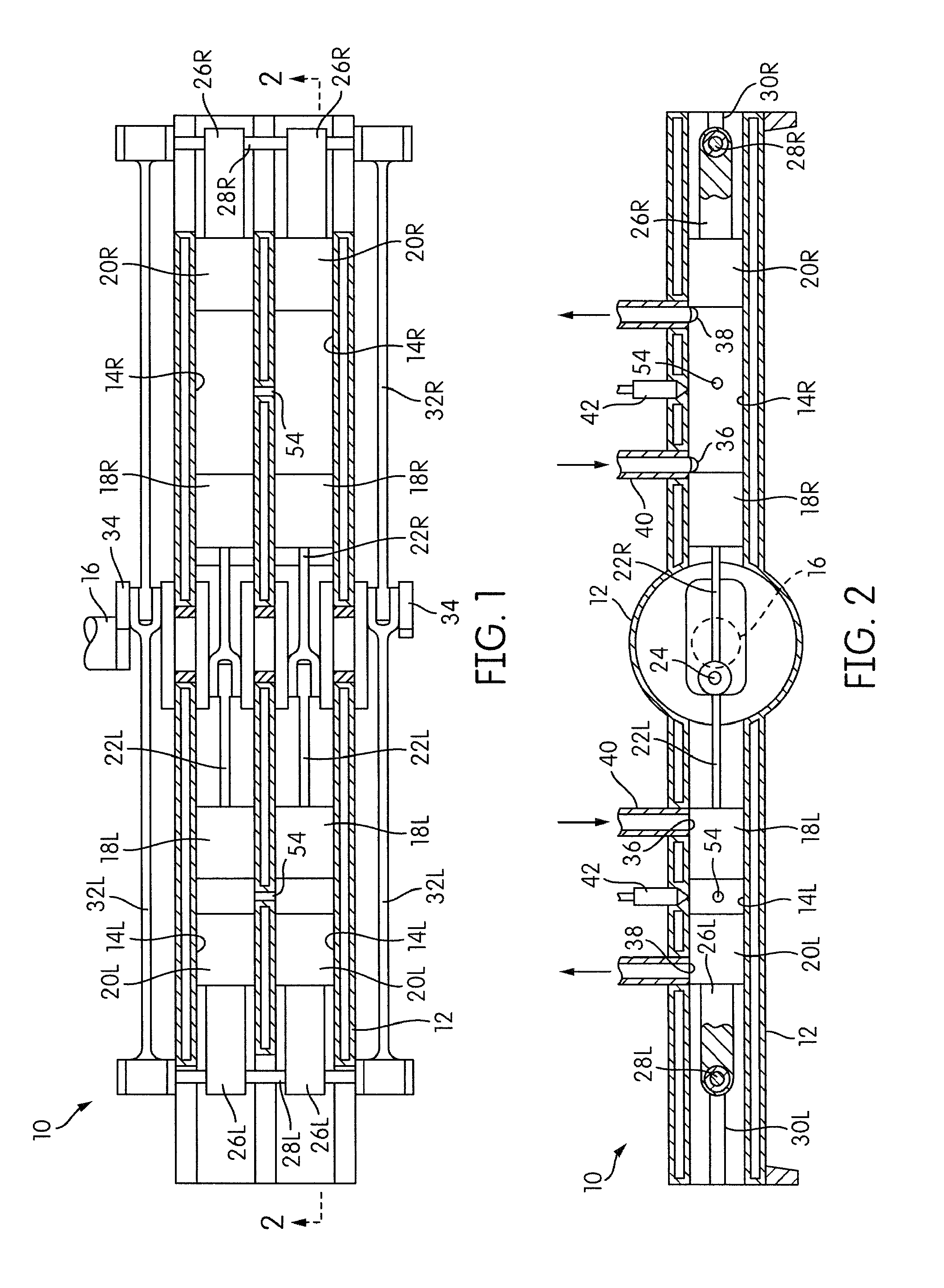
[0023]Referring more particularly to the drawings, there is shown in FIGS. 1 and 2 there of an internal combustion engine, generally indicated at 10, that embodies the principles of the present invention.
[0024]The engine 10 includes a main frame structure 12 shown illustratively as one piece in the drawings. In actuality, the frame may be made up of many conventional pieces. In the illustrative one piece embodiment shown the frame structure defines pairs of side by side cylinders 14L and 14R disposed in general alignment on opposite sides of an output crank shaft 16. Mounted within the pairs of cylinders 14L and 14R are pairs of opposed pistons 18L and 20L and 18R and 20R respectively.
[0025]The pair of pistons 18L are slidably sealingly mounted in the pair of cylinders 14L for simultaneous movements together toward and away from the crank shaft 16 by a pair of connecting rods 22L pivotally connected at one of their ends to the pair of pistons 18L (as by wrist pins not shown) with th...
PUM
 Abstract
Description
Claims
Application Information