Method and system for visual indication of the function of wireless receivers and a wireless receiver

a technology of visual indication and wireless receiver, which is applied in the direction of receiver monitoring, instruments, teaching apparatus, etc., can solve the problems of increasing power consumption, reducing range, and difficult for the caretaker to know whether the wireless system is actually working properly, and achieves the effect of simple system building

Active Publication Date: 2013-09-10
OTICON
View PDF8 Cites 1 Cited by
  • Summary
  • Abstract
  • Description
  • Claims
  • Application Information

AI Technical Summary

Benefits of technology

[0006]This greatly decreases the visual disturbance of the system and a missing flash on a single apparatus will easily be noticed by the caretaker, who by means of the synchronized flashing, will know when to observe a receiver of an individual pupil to spot if it is working or not.
[0008]In a preferred embodiment a carrier signal is used as the control signal, and when the carrier signal is detected, each receiver will start a timer used for controlling the flashing of the visual indicator. This allows a very simple system to be build based on a usual squelch function implemented in systems having a carrier signal. The squelch function suppresses the audio output whenever no carrier wave is received, and it is simple to use the same squelch function to suppress the visual indicator when no carrier signal is received, and to initiate a timer to control the visual indicator at the onset of reception of the carrier signal.
[0009]To synchronize flashing of the visual indicator, the carrier detection system is used as a common start point for all receivers. When a carrier is detected, each receiver will start a timer used for control of the flashing of a visual indicator. As the carrier is received simultaneously at each receiver, the timer will run in synchronized fashion in the receivers, and as the timer controls the on and off of the visual indicator, the indicator will turn on and off simultaneously on all receivers. If the receivers are already on channel before the transmitter starts transmitting, they will simultaneously detect the carrier when the transmitter is activated. This point of carrier detection will function as a common reference for the receivers, which thus allows them to flash their visual indicator synchronously.
[0011]Preferably a LED light is provided in each receiver and used as the visual indication. The advantages of the LED light are that it is power efficient and that it occupies very little space.

Problems solved by technology

When hearing impaired children are using wireless systems for educations or other purposes, it can be very difficult for the caretaker to know whether the wireless system is actually working properly.
However, having an LED on whenever the system is functional will increase power consumption and can cause technical problems like decreased range.
This solution introduces the following problem: A classroom full of students with wireless receivers, all flashing asynchronously, will be quite disturbing visually, and could cause loss of concentration for both the children and the caretaker.
Further, it can be quite difficult to spot a not-flashing device in the midst of all the flashing devices going on and off at random, and possibly a non-functional apparatus may pass un-noticed for quite a while because of this.

Method used


Image

  • Method and system for visual indication of the function of wireless receivers and a wireless receiver
  • Method and system for visual indication of the function of wireless receivers and a wireless receiver
  • Method and system for visual indication of the function of wireless receivers and a wireless receiver

Examples


Embodiment Construction

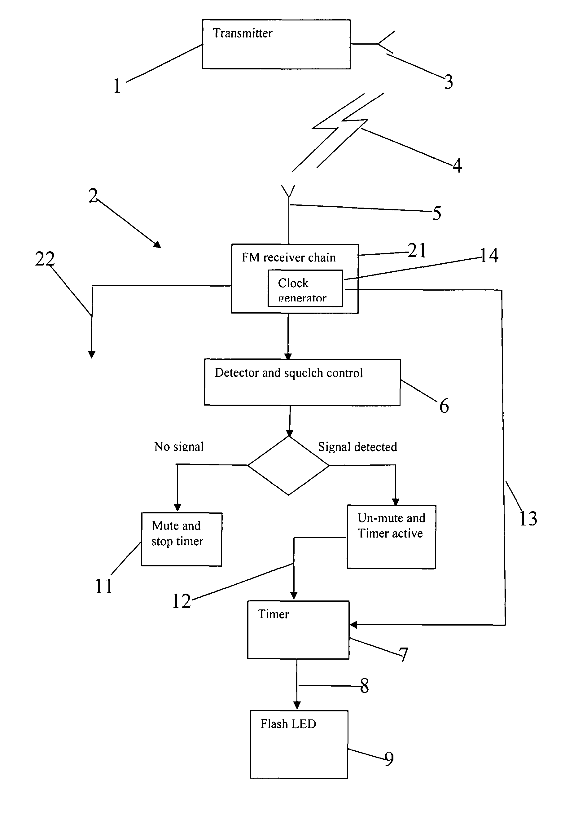
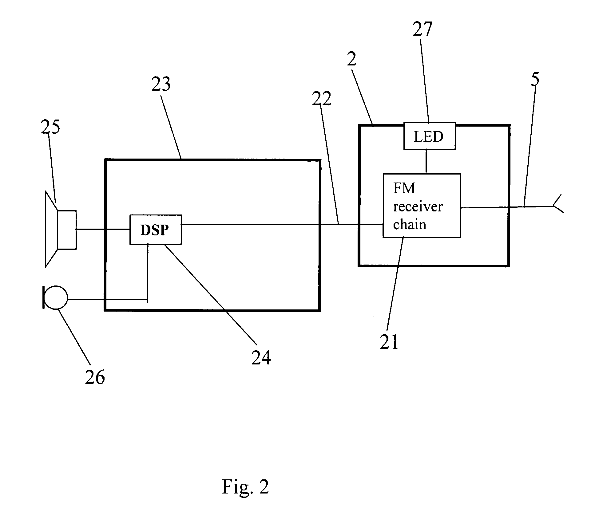
[0017]In FIG. 1 a transmitter 1 with an antenna 3 is schematically shown. The antenna 3 transmits a FM signal 4 which is received at the antennas 5 of a group of receivers whereof one receiver 2 is schematically illustrated. The FM receiver chain 21 receives the signal, and here it is converted to an audio signal 22 which may be served at a transducer to provide sound sensations for the user. The FM receiver 2 used in the described embodiment of the invention has a squelch functionality comprising a detector 6, which detects whether a proper FM carrier signal is present in the signal received at the antenna 5. If no proper FM carrier signal is detected at the squelch detector 6, a mute signal 11 is provided and no audio signal is presented to the user. This prevents the user from experiencing “radio noise” when there is no transmitter, or the transmitter is out of range. At the onset of detection of a suitable FM carrier signal, the mute is turned off and at the same time, a timer 7...


PUM


Abstract

A method for visual indication of the function of wireless receivers where a wireless signal is transmitted to a group of receivers, and where each receiver intermittently flashes a visual indicator when a wireless signal is received, whereby the intermittence and flashing of the visual indicators of the receivers are synchronized.

Description

AREA OF THE INVENTION[0001]The invention concerns class room or education systems where a wireless signal is transmitted from a transmitter to a group of receivers and whereby the wireless signal is received at each receiver and converted to an audio signal which is served at each wearer of a receiver in a form perceivable as sound.BACKGROUND OF THE INVENTION[0002]When hearing impaired children are using wireless systems for educations or other purposes, it can be very difficult for the caretaker to know whether the wireless system is actually working properly. Especially small children cannot report whether their receiver system is functional, thus a visual indication that the individual receiver is functional and is receiving properly can greatly improve ease of use for the caretaker. For this reason the OTICON FM receiver has an LED which will be lit when the system is functional and receiving the wireless signals.[0003]However, having an LED on whenever the system is functional ...

Claims


Application Information

Patent Timeline
Patent Type & Authority Patents(United States)
IPC IPC(8): G08B27/00
CPCH04B17/23
Inventor ANDERSEN, MARINUS
Owner OTICON
Why Eureka
Try Eureka