Lightning protection fastener, aircraft assembly, and method of manufacturing aircraft assembly component

a technology of aircraft assembly and lightning protection, which is applied in the direction of aircraft lighting protectors, fastening means, washers, etc., can solve the problems of affecting the ability of suppressing the occurrence of arcs, taking some work, and increasing the cost, and achieves low cost, high lightning protection capability, and light weight

Active Publication Date: 2013-11-19
MITSUBISHI AIRCRAFT
View PDF20 Cites 5 Cited by
  • Summary
  • Abstract
  • Description
  • Claims
  • Application Information

AI Technical Summary

Benefits of technology

[0021]The present invention has been accomplished based on the technological problems described above, and has an object of providing a long-life lightning protection fastener to prevent explosion for an aircraft at low cost, the fastener having a light weight, ensuring sufficient lightning protection capability, and having extremely less failures and high reliability, and also providing an aircraft assembly and a method of manufacturing an aircraft assembly component.
[0026]By interposing the insulating ring member in a compressed state between at least one of the outer perimeter part of the head of the fastener body and the outer perimeter part of the fastening member, and the members, a space where an electric discharge can occur near an interface between the head of the fastener body or the outer perimeter part of the fastening member, and the members is eliminated, and the occurrence of an arc at such a position as the position c) described above can be prevented. Also, even if an arc occurs, an electric discharge of the generated arc and hot particles flying therefrom can be prevented from being in contact with flammable fuel vapor.
[0028]The groove may have a tapered surface with a diameter gradually reduced as being away from the members. With such configuration, the ring member is less prone to be detached from the groove.
[0033]When one of the two members is a fuel tank, a sealing material for preventing fuel from leaking from the one member to the other member may be applied onto at least one of an interface between the two members, an interface between the fastener body and the two members, and a portion between a tip of the fastener body and the fastening member.
[0038]According to the present invention, with the insulating ring member being interposed in a compressed state between at least one of the outer perimeter part of the head of the fastener body and the outer perimeter part of the fastening member, and the members, an interface between the two members and the head of the fastener body and the fastening member can be sealed. Therefore, a high lightning protection (explosion prevention) capability at low cost and having a light weight and sufficient and extremely high reliability can be ensured. Furthermore, with the structure in which the ring member is securely interposed in a compressed state between the members and the fastener body, the ring member does not come off at the time of manufacturing or operation of the aircraft.

Problems solved by technology

However, even in the technology described in Japanese Patent Application Laid-Open No. 2010-254287 as described above, it is required to fill the inside of the cap with a sealant in order to ensure insulation, thereby taking some work.
Moreover, the sealant is required to be stored at low temperature before work, and its consumable period is short after the sealant is exposed to an environment at room temperature, which is a factor of increasing cost.
Then, even with the technology described in Japanese Patent Application Laid-Open No. 2010-254287, although not as much as the technology disclosed in “Lightning Protection of Aircraft” described above, there is a possibility of an adverse effect in capability of suppressing the occurrence of an arc.

Method used


Image

  • Lightning protection fastener, aircraft assembly, and method of manufacturing aircraft assembly component
  • Lightning protection fastener, aircraft assembly, and method of manufacturing aircraft assembly component
  • Lightning protection fastener, aircraft assembly, and method of manufacturing aircraft assembly component

Examples


first embodiment

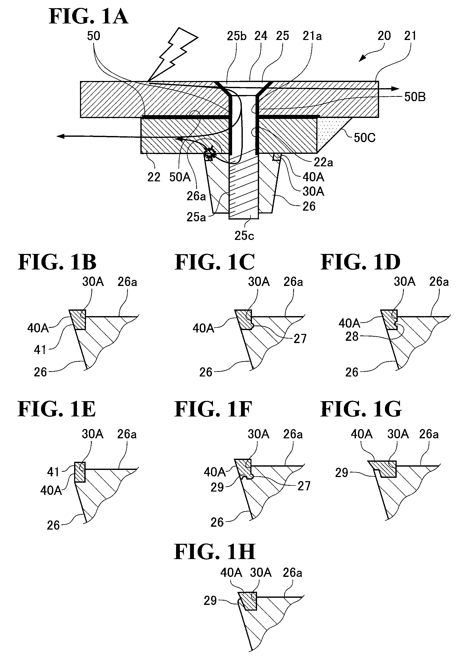
[0054]FIGS. 1A to 1H are sectional views of part of a wing configuring an airframe of an aircraft to which a lightning protection fastener in a first embodiment described below is applied.

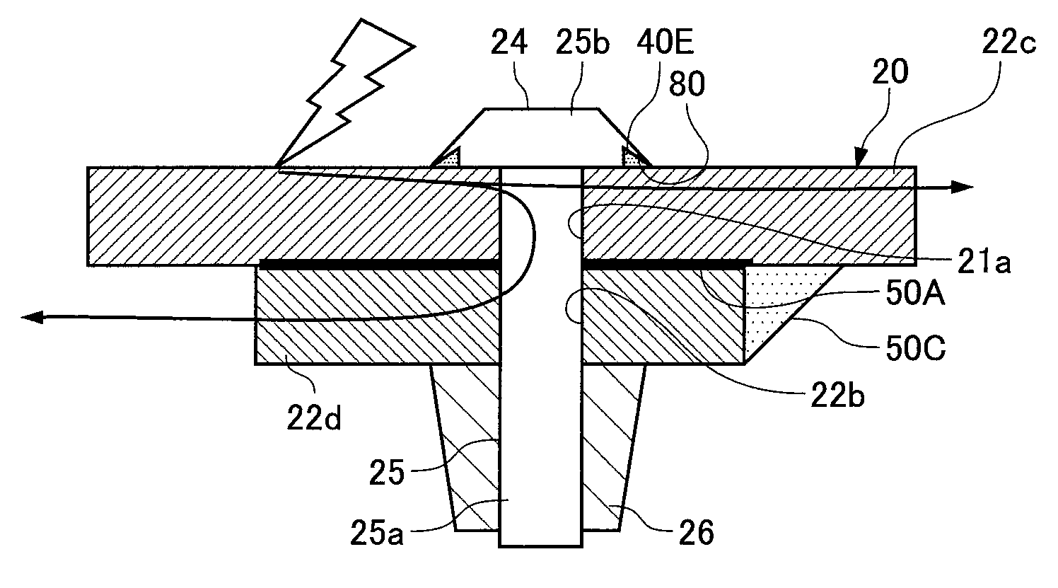
[0055]As shown in FIG. 1A, a wing (an aircraft assembly) 20 has a shell formed of a wing panel (member) 21 made of, for example, a metal material such as aluminum alloy, CFRP (Carbon Fiber Reinforced Plastics), which is a composite material made of a carbon fiber and a resin, or GFRP (Glass Fiber Reinforced Plastics), which is a composite material made of a glass fiber and a resin. A structural member for reinforcement (such as a rib), a fuel tank and various devices provided inside the wing 20 are fixed to the wing panel 21 via a member 22 such as a stay made of a metal material such as an aluminum alloy or a composite material. The member 22 such as a stay is mounted on the wing panel 21 by a fastener member 24.

[0056]Although not shown in the drawings, when the wing panel 21 is made of a composit...

second embodiment

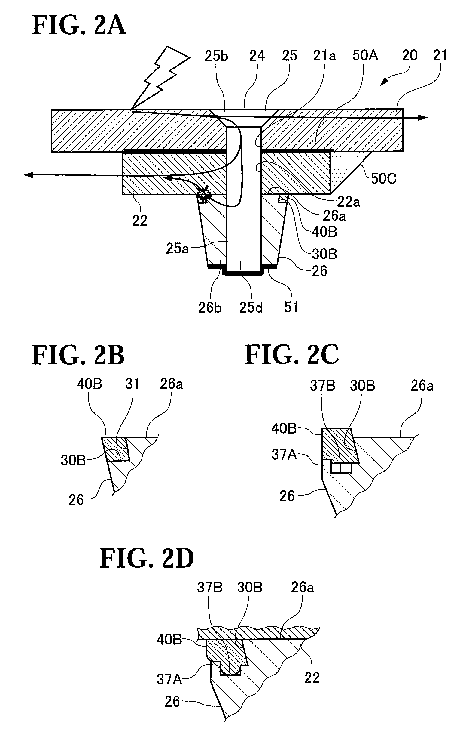
[0103]As shown in FIG. 2A, a ring member 40B in the present embodiment is fitted in a groove 30B formed on the outer perimeter part of the collar 26.

[0104]Here, as shown in FIG. 2B, the groove 30B is formed to be tapered so that an inner diameter of an inner perimeter wall surface 31 of the groove 30B is gradually reduced as going from a contact surface 26a side of the collar 26 toward its opposite side.

[0105]The ring member 40B also has a sectional shape formed so as to fit in this groove 30B.

[0106]According to the structure as described above, the ring member 40B is in intimate contact with both of the member 22 and the collar 26 to seal the interface with the member 22, thereby preventing and sealing the occurrence of an arc at an outer perimeter edge part of the collar 26.

[0107]Furthermore, since the inner perimeter wall surface 31 of the groove 30B is tapered, the ring member 40B is less prone to come off from the collar 26. Thus, it is possible to prevent a situation such that...

third embodiment

[0111]As shown in FIGS. 3A and 3B, a groove 30C in which a ring member 40C is fitted in the present embodiment has a tapered surface 32 formed in a tapered shape so that its inner diameter is gradually reduced as going from the contact surface 26a side of the collar 26 toward its opposite side. Furthermore, edge parts 33A and 33B adjacent to an inner perimeter surface of the groove 30C and the contact surface 26a and an outer perimeter surface 26c of the collar 26 are formed so as to have obtuse angles θ1 and θ2, respectively. Also, the groove 30C has a pushing surface 36 formed nearly parallel to the contact surface 26a of the collar 26 to push the ring member 40C onto the member 22.

[0112]The ring member 40C has a sectional shape formed so as to fit in the groove 30C.

[0113]According to the structure as described above, the ring member 40C is in intimate contact with both of the member 22 and the collar 26 to seal the interface with the member 22, thereby preventing and sealing the ...


PUM

PropertyMeasurementUnit
temperatureaaaaaaaaaa
stressaaaaaaaaaa
temperatureaaaaaaaaaa

Abstract

A long-life lightning protection fastener or the like to prevent explosion for aircrafts at low cost is provided, the fastener having a light weight, ensuring sufficient lightning protection, and having extremely less failures and high reliability. A ring-shaped ring member 40A made of resin is mounted on a collar 26. This ring member 40A is interposed between a member 22 and the collar 26 and is in intimate contact with both of the member 22 and the collar 26, thereby sealing an interface with the member 22 for sealing and preventing the occurrence of an arc at an outer perimeter edge of the collar 26.

Description

BACKGROUND OF THE INVENTION[0001]1. Field of the Invention[0002]The present invention relates to a lightning protection fastener to prevent explosion for use in a portion where there is a possibility of the presence of flammable fuel vapor, such as a fuel tank placed in an airframe of an aircraft, in particular, in a wing or a body thereof, and also relates to an aircraft assembly and a method of manufacturing aircraft assembly component.[0003]2. Description of the Related Art[0004]A wing partly constituting an airframe of an aircraft generally has a hollow structure. A wing-surface panel forming a wing surface is fixed to a structural member inside the wing with a fastener member (a fastener).[0005]In this case, the fastener member fastens the wing-surface panel and the structural member together, with a pin-shaped fastener body being inserted from outside of the wing into through holes formed on both of the wing-surface panel and the structural member inside of the wing and its ti...

Claims


Application Information

Patent Timeline
Patent Type & Authority Patents(United States)
IPC IPC(8): H05F3/00
CPCB64D45/02F16B43/001F16B5/0258Y10T29/49947
Inventor YAMAKOSHI, HIDEOKAMINO, YUICHIROASAHARA, YUJIWATANABE, YASUNORIIYOMASA, ATSUHIROHASHIGAMI, TORUMURAKAMI, KOHEIOKUMURA, TOMONORI
Owner MITSUBISHI AIRCRAFT
Why Eureka
Try Eureka