

Method and apparatus for radio antenna frequency tuning
a radio antenna and frequency tuning technology, applied in the direction of resonant antennas, transmission monitoring, receiver monitoring, etc., can solve the problems of affecting the performance of antennas, the designer is forced to compromise the performance in some frequency bands, and the antenna cannot radiate efficiently at all frequencies
- Summary
- Abstract
- Description
- Claims
- Application Information
AI Technical Summary
Benefits of technology
Problems solved by technology
Method used
Image

Examples
Embodiment Construction
[0013]The present disclosure provides a method and apparatus for radio antenna frequency tuning. One or more exemplary embodiments can employ an open loop mechanism to solve the fundamental problems associated with antenna performance over a range of frequencies and use cases.
[0014]One or more exemplary embodiments can address applying tuning to changing antenna environments without the need for, or use of, a direct feedback loop from the antenna. However, other embodiments can utilized a combination of open loop and closed loop feedback.
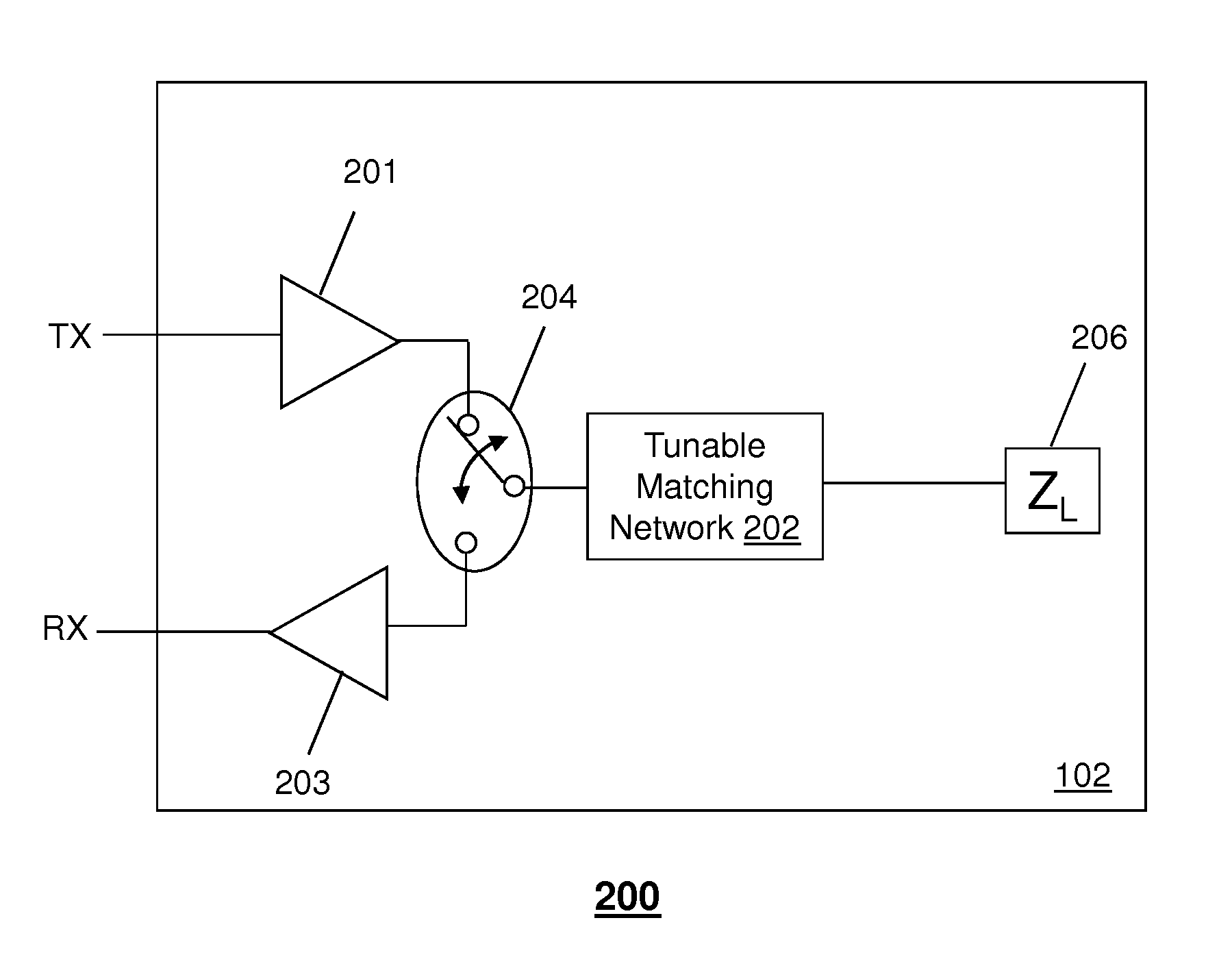
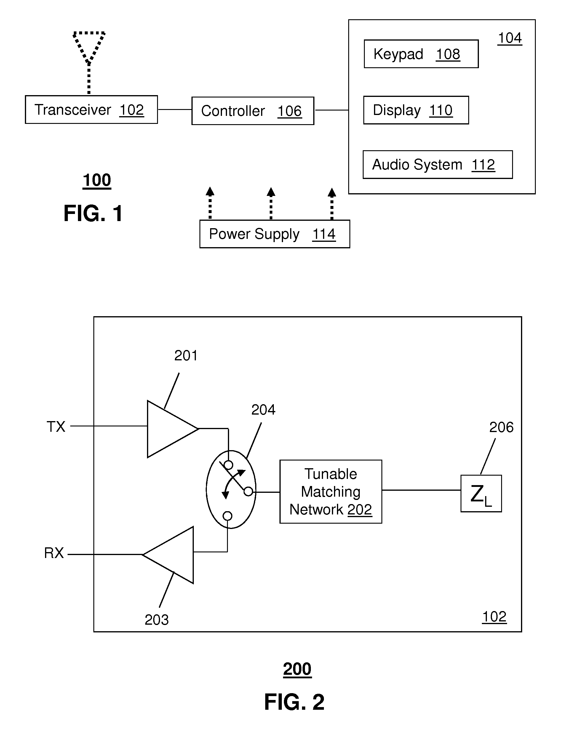
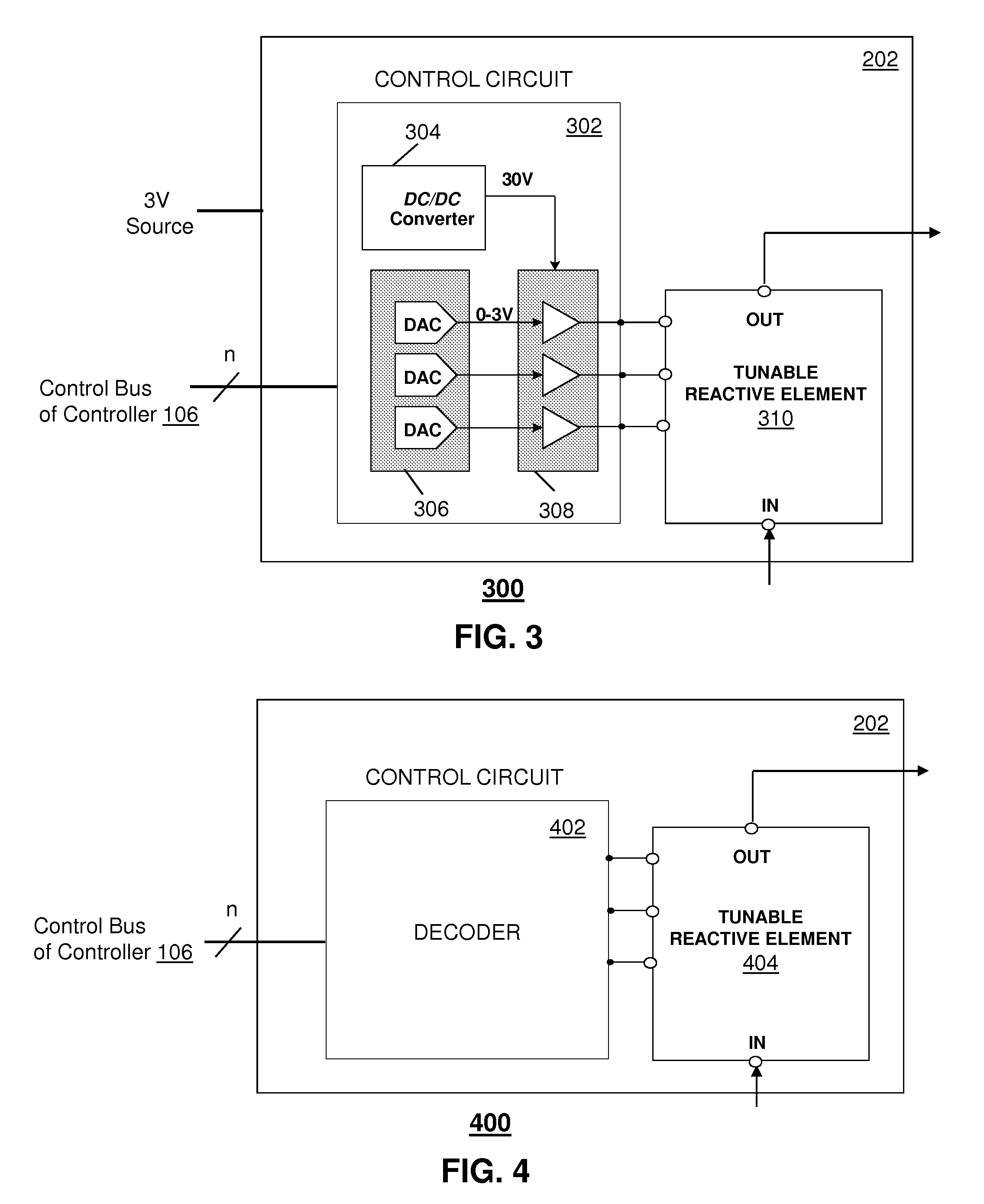
[0015]One embodiment of the present disclosure entails a method to select a tuning state of a tunable matching network operable in a communication device, where the tunable matching network has a tunable reactance that affects one or more performance parameters of the communication device. The method can include performing the selection of the tuning state based on radio frequency and incomplete information about the antenna environment without dire...
PUM
 Abstract
Description
Claims
Application Information