Variable performance building cladding according to view angle

Inactive Publication Date: 2012-01-26
BOTKE MATTHEW MURRAY
View PDF18 Cites 14 Cited by
  • Summary
  • Abstract
  • Description
  • Claims
  • Application Information

AI Technical Summary

Benefits of technology

[0047]Further, visual appearance can be varied within surfaces and across surfaces to establish visual impact and interest thereby reducing the relative visual perception and impact of transitions from predominantly sun-facing and predominantly observer-facing surfaces. Patterns may be comprised of any combination of visible artifacts such as aspects of color, texture, or surface finish. As but one example of accomplishing variable appearance on an inclined building surface according to this invention is by printing patterns (46) during the coating process or as a secondary process. Visual perceptible impact of surfaces and coatings according to this invention is more effectively reduced by incorporating patterns using visual contrast having spatial frequency similar to the surface profile wavelength. Patterns may be applied to predominantly observer-facing, predominantly sun-facing, transitional interconnecting surfaces or any combination of surfaces. Patterns that visually extend beyond individual surfaces have visual impact and reduce sensitivity to the generally regular periodicity of surface profiles according to this invention. Apparently random or pseudo random and or repeating patterns are utilized to reduce the visual impact of transitions between predominantly observer-facing and predominantly sun-facing surfaces in the scene of persons viewing the building surface from common viewing positions.
[0048]A third contemplated embodiment of the present invention is illustrated in FIG. 5 as a concrete or clay roof tile. Tiles are generally molded or extruded in various profiles. Methods and features for assembling the tile into a contiguous weather resistant cladding such as a gutter (57), side lap (58), and h

Problems solved by technology

Heat energy transfer through the building envelope changes the temperature of the interior space and can therefore become uncomfortable.
The rate of energy transfer across the building envelope becomes significant when large temperature differences exist between the ambient environment and the interior space.
Traditionally, the energy required to

Method used


Image

  • Variable performance building cladding according to view angle
  • Variable performance building cladding according to view angle
  • Variable performance building cladding according to view angle

Examples


Example

DETAILED DESCRITPION OF THE INVENTION

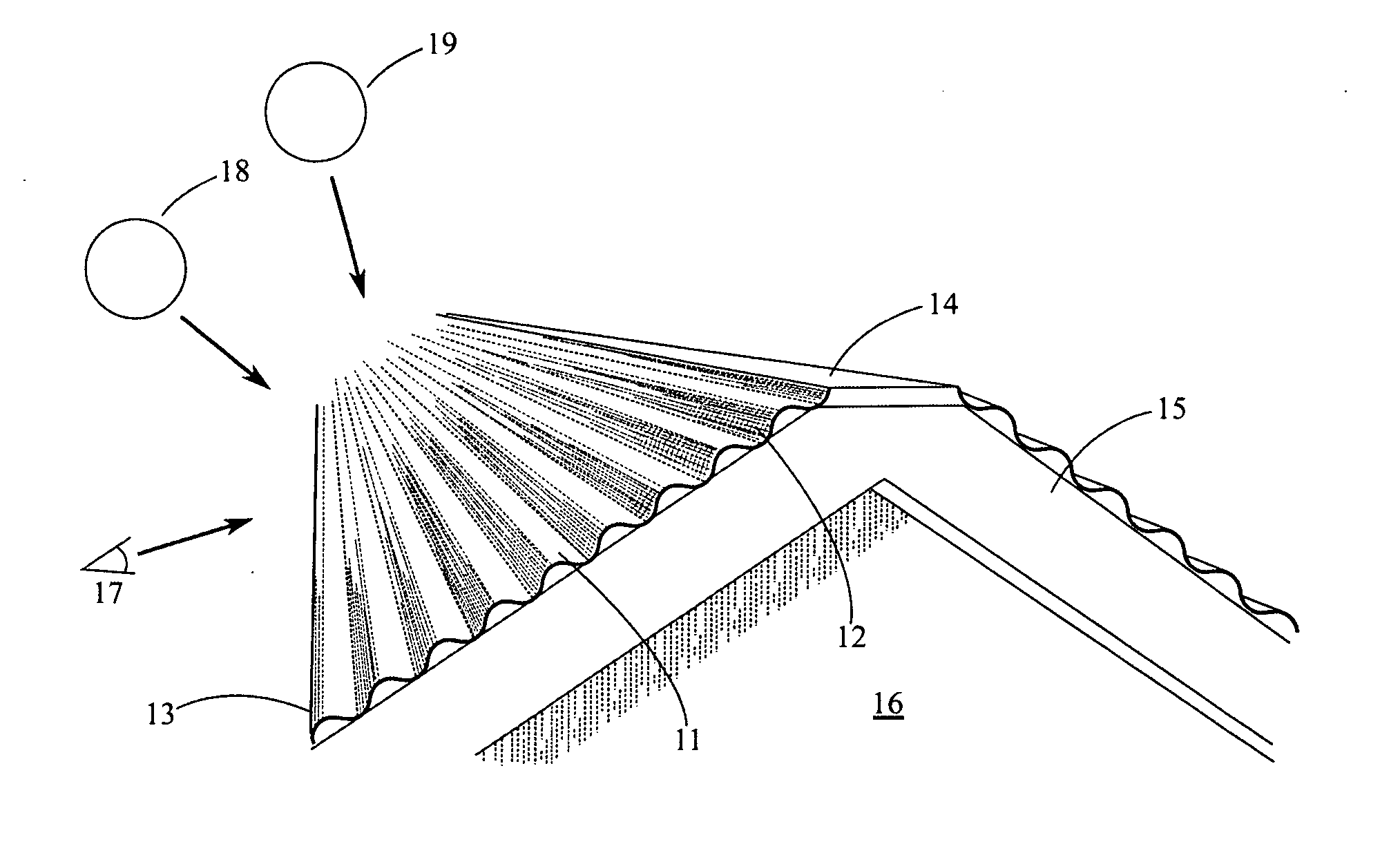
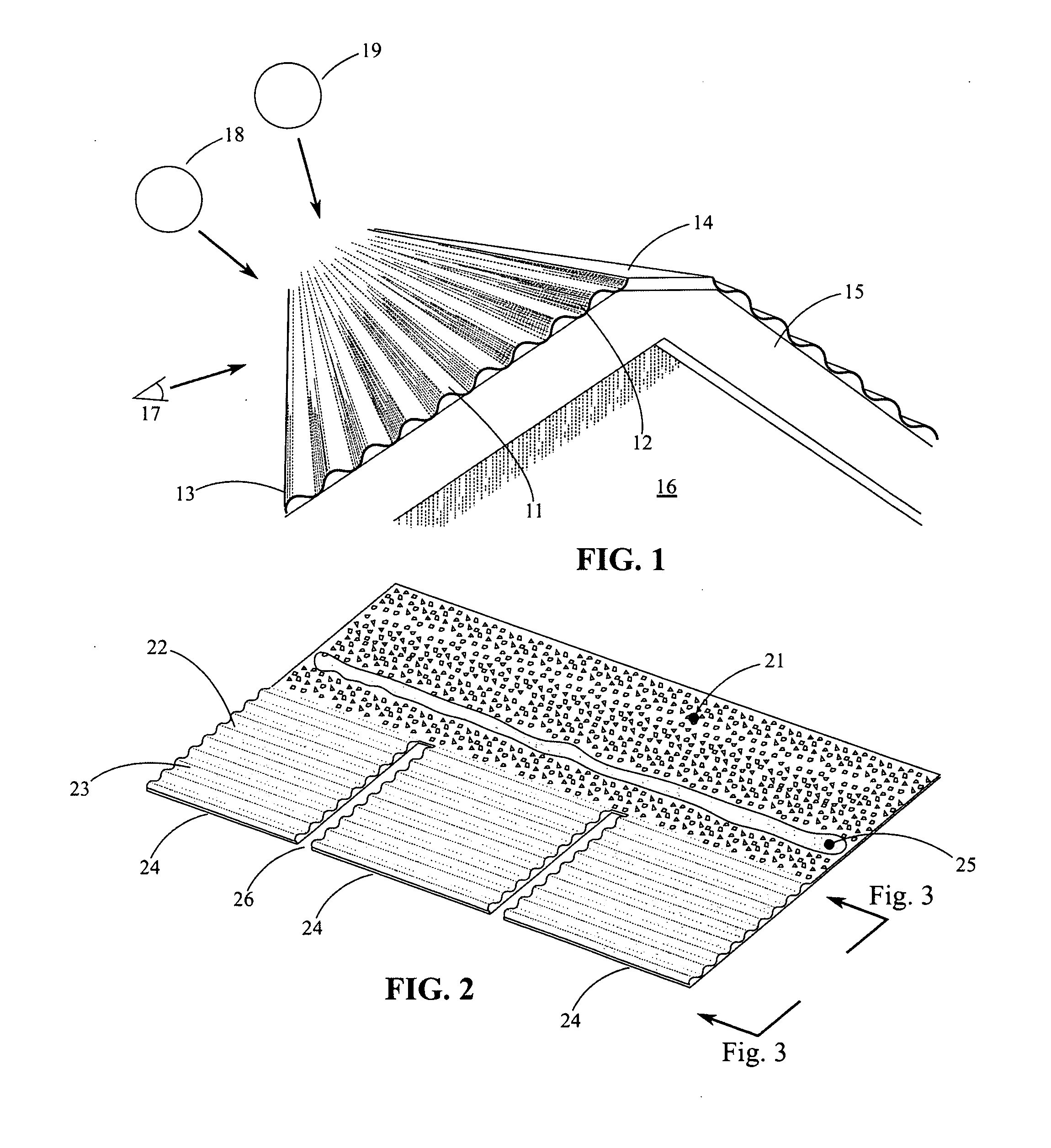
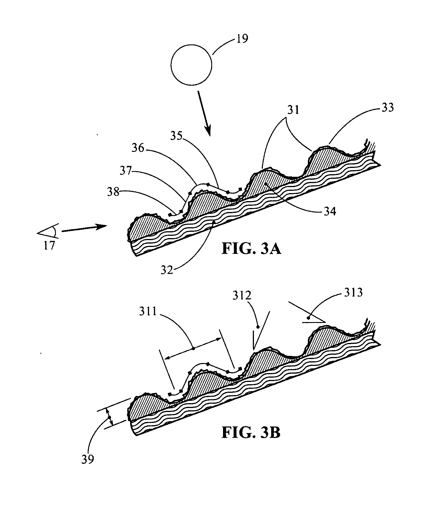
[0037]An inclined building outer surface reflectively responsive to sun elevation angle is disclosed having high ornamental quality over a wide range of common viewing positions and applicable to a wide range of incline angles. In embodiments according to the present invention, surfaces are adapted to appear with non-constant and perhaps continually varying contrast and or reflectivity across surfaces for a given surface profile wavelength based on the human eye contrast sensitivity function and visual perception. An inclined building outer surface according to this invention therefore has wide applicability to a large range of roof slopes thereby increasing cost-effectiveness, reducing visual impact of surface profiles, and simplifying installation while maintaining acceptable energy performance. Embodiments of the present invention are currently contemplated as tiles, panels, shingles, membranes, granulated roll roofing and other materials know...


PUM


Abstract

This invention relates to inclined outer building surfaces such as roofs reflectively responsive to sun elevation angle and predominantly ornamental when viewed from common viewing positions. More specifically, this invention relates to methods of sizing, shaping, surface characteristics, and coating resulting in improved performance, increased ornamental quality, improved economy of roofing of this class using human eye contrast sensitivity and visual perception.

Description

CROSS REFERENCE TO RELATED APPLICATIONS[0001]This application claims priority to U.S. Provisional Application No. 61 / 367,477 filed on Jul. 26, 2010.STATEMENT REGARDING FEDERALLY SPONSORED RESEARCH OR DEVELOPMENT[0002]Not ApplicableTHE NAMES OF THE PARTIES TO A JOINT RESEARCH AGREEMENT[0003]Not ApplicableREFERENCE TO SEQUENCE LISTING, A TABLE OR A COMPUTER PROGRAM LISTING COMPACT DISC APPENDIX[0004]Not ApplicableBACKGROUND OF THE INVENTION[0005]Heat energy transfer through the building envelope changes the temperature of the interior space and can therefore become uncomfortable. Energy must be expended to maintain the desired temperature if this space is conditioned in order to offset energy transfer to or from the environment. Therefore, minimal energy transfer across the envelope is desirable. The rate of energy transfer across the building envelope becomes significant when large temperature differences exist between the ambient environment and the interior space. A primary source ...

Claims


Application Information

Patent Timeline
IPC IPC(8): E04B7/02
CPCE04D1/04E04D1/16E04D2001/005E04D3/30E04D1/26E04D1/2916E04D1/02
Inventor BOTKE, MATTHEW MURRAY
Owner BOTKE MATTHEW MURRAY
Why Eureka
Try Eureka