
Lead frame for connecting optical sub-assembly to printed circuit board

a technology of printed circuit board and lead frame, which is applied in the direction of optical elements, coupling device connections, instruments, etc., can solve the problems of unfavorable rf response, flex circuits represent a significant portion of the cost and labor required to manufacture transceiver modules, and flex circuit costs continue to represent an increasing proportion of the overall cost of transceiver modules. achieve the effect of reliable and inexpensive manner

Inactive Publication Date: 2005-09-01
II VI DELAWARE INC
View PDF15 Cites 13 Cited by
  • Summary
  • Abstract
  • Description
  • Claims
  • Application Information

AI Technical Summary

Benefits of technology

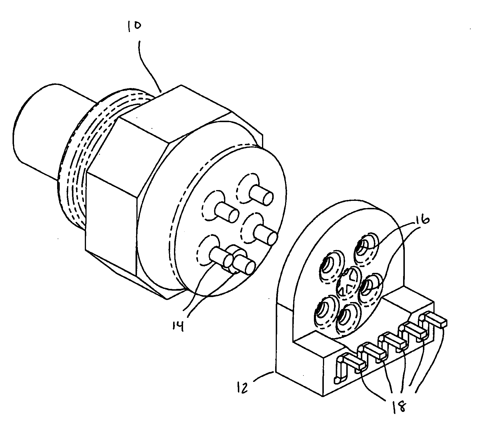
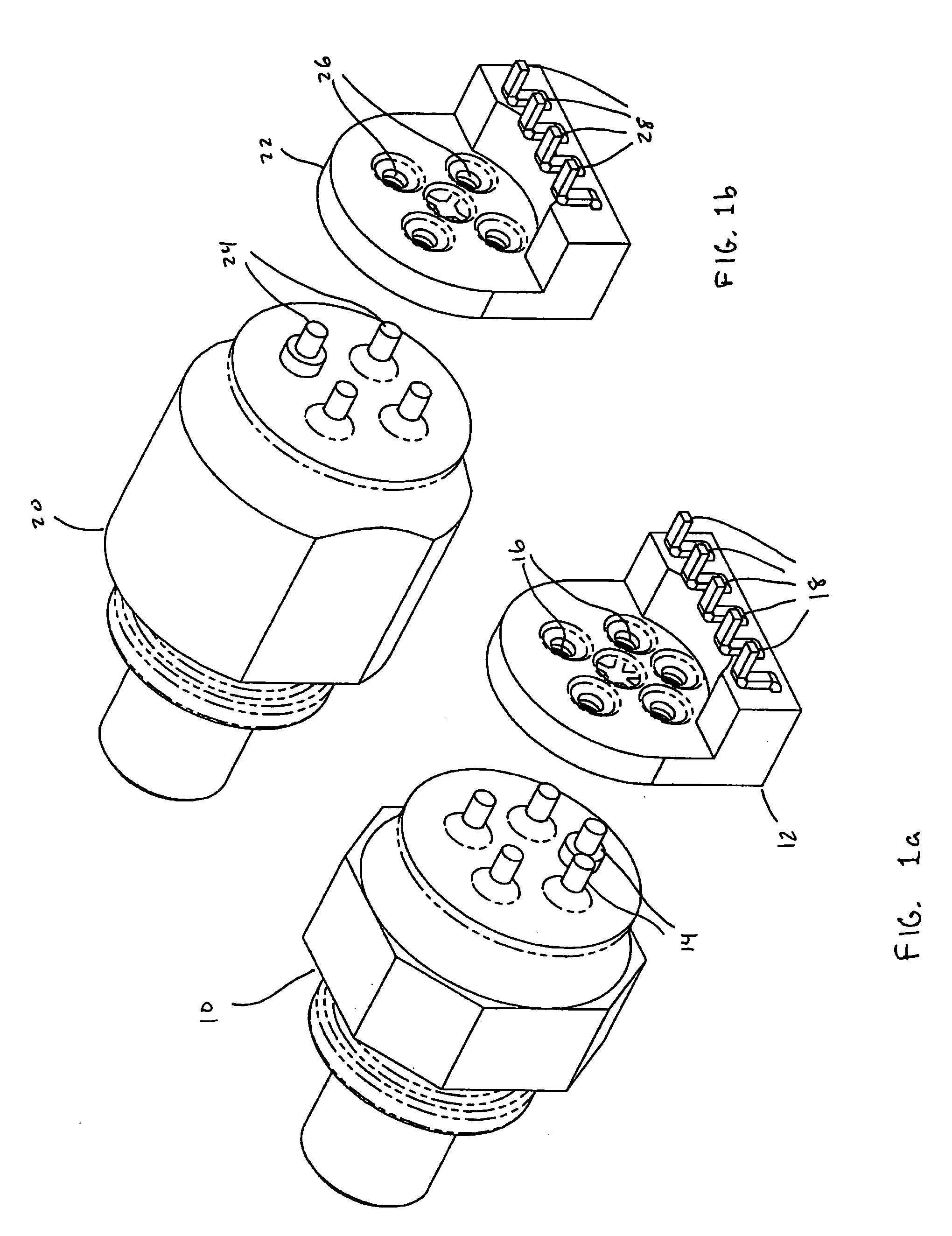
[0011] The present invention relates to lead frame connectors that are used to electrically and mechanically connect optical sub-assemblies to printed circuit boards in optical transceiver modules. The lead frame connectors enable optical sub-assemblies to be connected to the printed circuit board in optical transceiver modules in a reliable and inexpensive manner. The use of such lead frame connectors eliminates the need for flexible printed circuit boards that have been used in conventional transceiver modules.
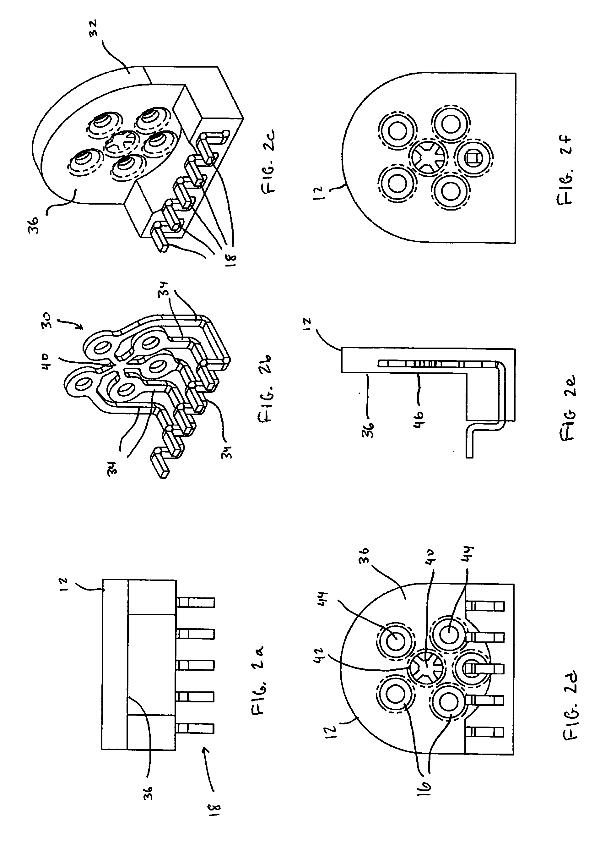
[0013] One advantage of the lead frame connectors is that they can be designed to yield desirable electrical performance and RF response. These results can be achieved because of the ability to control impedances based on the fact that the width and shape of the conductors and the gaps between conductors can be carefully controlled. In addition, the electrical properties of the plastic material used in the molded casing can be considered when designing for desirable electrical response.

Problems solved by technology

While flex circuits have been widely used in recent years in optical transceiver modules, flex circuits represent a significant portion of the costs and labor required to manufacture transceiver modules.
As the price of transceiver modules drops, the costs associated with flex circuits continue to represent an increasing proportion of the overall costs of transceiver modules.
This technique is often less expensive than the use of flex circuits, but can lead to unfavorable RF response due to the inability to carefully control impedances.
In addition, machining leads of TOSAs and ROSAs introduces reliability risks due to the likelihood of damaging glass or other fragile portions of header assemblies in TOSAs and ROSAs that enclose the lasers and photodetectors, respectively.
Because of the possibility of damaging the TOSAs and ROSAs and poor electrical performance, bending leads to enable the optical sub-assemblies to be directly connected to the printed circuit board is not suitable for many transceiver modules.
This approach is particularly unsuitable for relatively high-speed transceiver modules, in which the RF response of the conductors is more important.

Method used


Image

  • Lead frame for connecting optical sub-assembly to printed circuit board
  • Lead frame for connecting optical sub-assembly to printed circuit board
  • Lead frame for connecting optical sub-assembly to printed circuit board

Examples


Embodiment Construction

[0011] The present invention relates to lead frame connectors that are used to electrically and mechanically connect optical sub-assemblies to printed circuit boards in optical transceiver modules. The lead frame connectors enable optical sub-assemblies to be connected to the printed circuit board in optical transceiver modules in a reliable and inexpensive manner. The use of such lead frame connectors eliminates the need for flexible printed circuit boards that have been used in conventional transceiver modules.

[0012] According to one embodiment, the lead frame connector includes a stamped and bent conductive lead structure that is encased within an insert injection molded plastic casing. The plastic casing provides electrical insulation for the conductors in the lead frame as well as mechanical support for the finished component. The lead frame connectors connect to the leads associated with the optical sub-assemblies. The lead frame connectors also can be surface mounted onto th...


PUM


Abstract

Lead frame connectors for connecting optical sub-assemblies to printed circuit boards in optical transceiver modules. The lead frame connectors include a stamped and bent conductive lead structure that is encased in an insert injection molded plastic casing. The plastic casing provides electrical insulation for the conductors in the lead frame as well as mechanical support for the finished component. The lead frame connectors connect to the leads associated with the optical sub-assemblies and are surface mounted onto the printed circuit board to establish connectivity between the optical sub-assembly and the printed circuit board. The lead frame assemblies are generally more reliable and less expensive than using flexible printed circuit board structures to establish electrical connectivity between optical sub-assemblies and transceiver printed circuit boards.

Description

RELATED APPLICATION [0001] This application claims the benefit of U.S. Provisional Patent Application Ser. No. 60 / 548,846, filed Feb. 27, 2004, which is incorporated herein by reference.BACKGROUND OF THE INVENTION [0002] 1. The Field of the Invention [0003] The present invention relates generally to optical transceiver modules. More specifically, the present invention relates to lead frame connectors used to connect an optical sub-assembly to a printed circuit board in an optical transceiver module. [0004] 2. Background and Relevant Art [0005] Optical transceivers are used to transmit and receive optical signals from an optical network and to enable electrical network components to interface with and communicate over optical networks. Many optical transceivers are modular and are designed in accordance with industry standards that define mechanical aspects of the transceivers, form factors, optical and electrical requirements, and other characteristics and requirements of the transc...

Claims


Application Information

Patent Timeline
IPC IPC(8): G02B6/42H01R12/00
CPCG02B6/4201
Inventor ICE, DONALD A.
Owner II VI DELAWARE INC
Learn More