

Methods for manufacturing optical modules having an optical sub-assembly
a technology of optical sub-assembly and manufacturing method, which is applied in the direction of manufacturing tools, instruments, optical elements, etc., can solve the problems of increasing the cost of flex circuits, reducing the reliability of flex circuits, and reducing the overall cost of transceiver modules, so as to achieve reliable and inexpensive methods
- Summary
- Abstract
- Description
- Claims
- Application Information
AI Technical Summary
Benefits of technology
Problems solved by technology
Method used
Image

Examples
Embodiment Construction
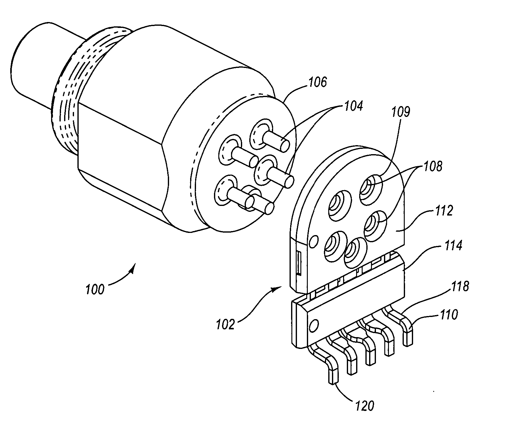
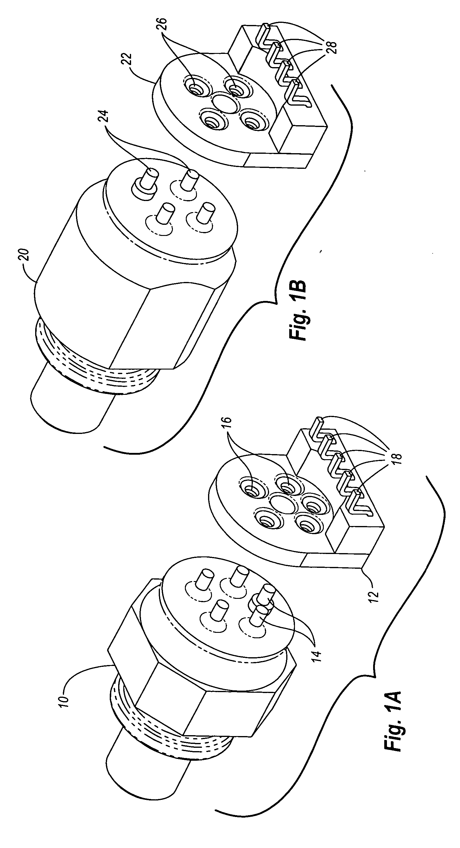
[0011] The present invention relates to methods for manufacturing or assembling optical transceiver modules using lead frame connectors that electrically and mechanically connect optical sub-assemblies to printed circuit boards. The lead frame connectors enable optical sub-assemblies to be connected to the printed circuit board in optical transceiver modules in a reliable and inexpensive manner. The use of such lead frame connectors eliminates the need for flexible printed circuit boards that have been used in conventional transceiver modules.
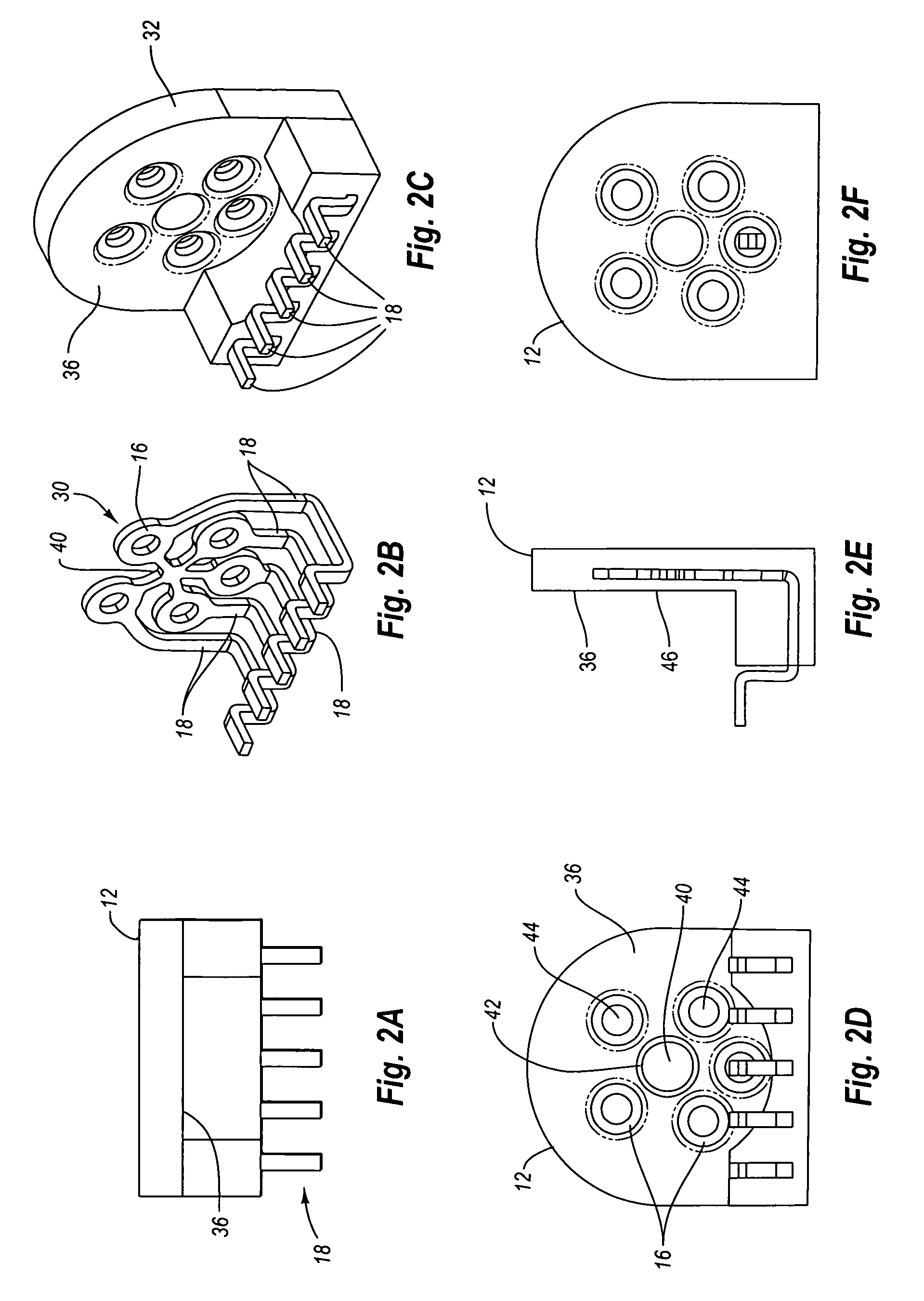
[0012] According to one embodiment, the lead frame connector includes an electrically insulating case having a first part separated from a second part. The connector also has a plurality of conductors that are electrically isolated one from another by the electrically insulating case. Each of the plurality of conductors can form an electrical contact restrained in a fixed position with respect to the first part and a contact point extending fr...
PUM
| Property | Measurement | Unit |
|---|---|---|
| dielectric constant | aaaaa | aaaaa |
| dielectric constant | aaaaa | aaaaa |
| dielectric constant | aaaaa | aaaaa |
Abstract
Description
Claims
Application Information