

Methods for manufacturing lead frame connectors for optical transceiver modules
a technology of optical transceiver module and lead frame, which is applied in the direction of contact member manufacturing, coupling device connection, and connection formation by deformation, etc., can solve the problems of unfavorable rf response, flex circuits represent a significant portion of the cost and labor required to manufacture transceiver modules, and flex circuit costs continue to represent an increasing proportion of the overall cost of transceiver modules. achieve the effect of reliable and inexpensive manner
- Summary
- Abstract
- Description
- Claims
- Application Information
AI Technical Summary
Benefits of technology
Problems solved by technology
Method used
Image

Examples
Embodiment Construction
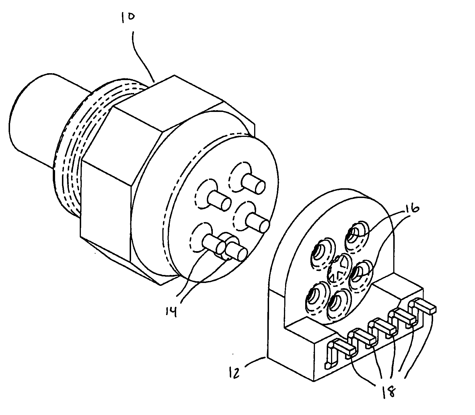
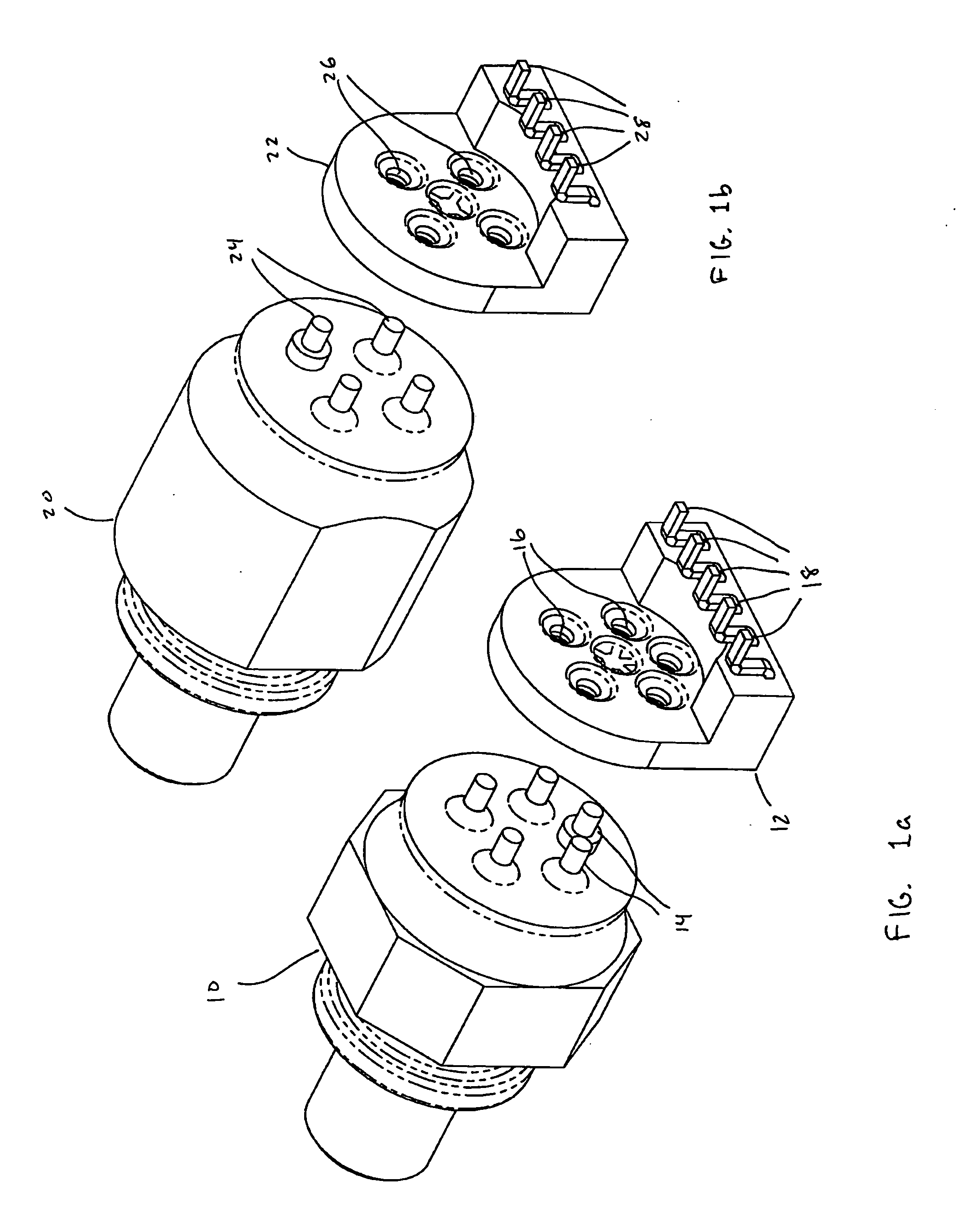
[0011] The present invention relates to lead frame connectors that are used to electrically and mechanically connect optical sub-assemblies to printed circuit boards in optical transceiver modules. The lead frame connectors enable optical sub-assemblies to be connected to the printed circuit board in optical transceiver modules in a reliable and inexpensive manner. The use of such lead frame connectors eliminates the need for flexible printed circuit boards that have been used in conventional transceiver modules.
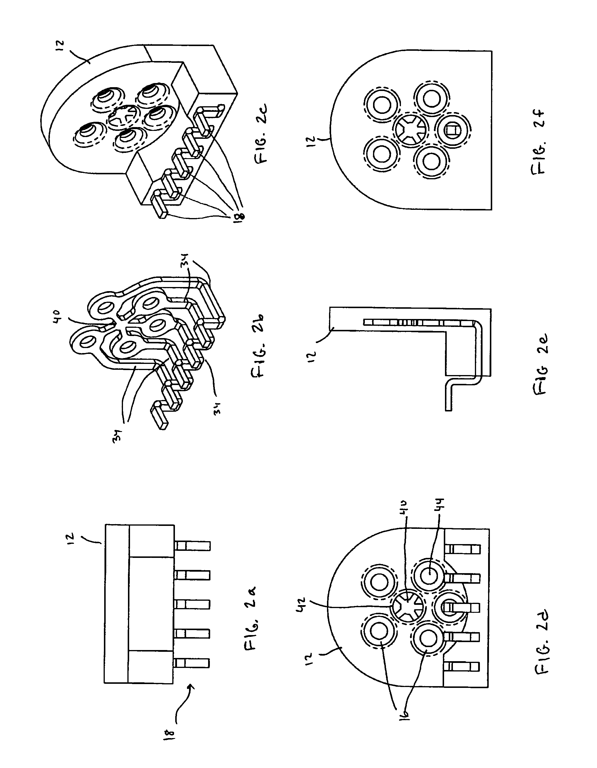
[0012] According to one embodiment, the lead frame connector includes a stamped and bent conductive lead structure that is encased within an insert injection molded plastic casing. The plastic casing provides electrical insulation for the conductors in the lead frame as well as mechanical support for the finished component. The lead frame connectors connect to the leads associated with the optical sub-assemblies. The lead frame connectors also can be surface mounted onto th...
PUM
| Property | Measurement | Unit |
|---|---|---|
| conductive | aaaaa | aaaaa |
| optical sub-assembly | aaaaa | aaaaa |
| optical signal | aaaaa | aaaaa |
Abstract
Description
Claims
Application Information