

Methods for manufacturing optical modules using lead frame connectors
- Summary
- Abstract
- Description
- Claims
- Application Information
AI Technical Summary
Benefits of technology
Problems solved by technology
Method used
Image

Examples
Embodiment Construction
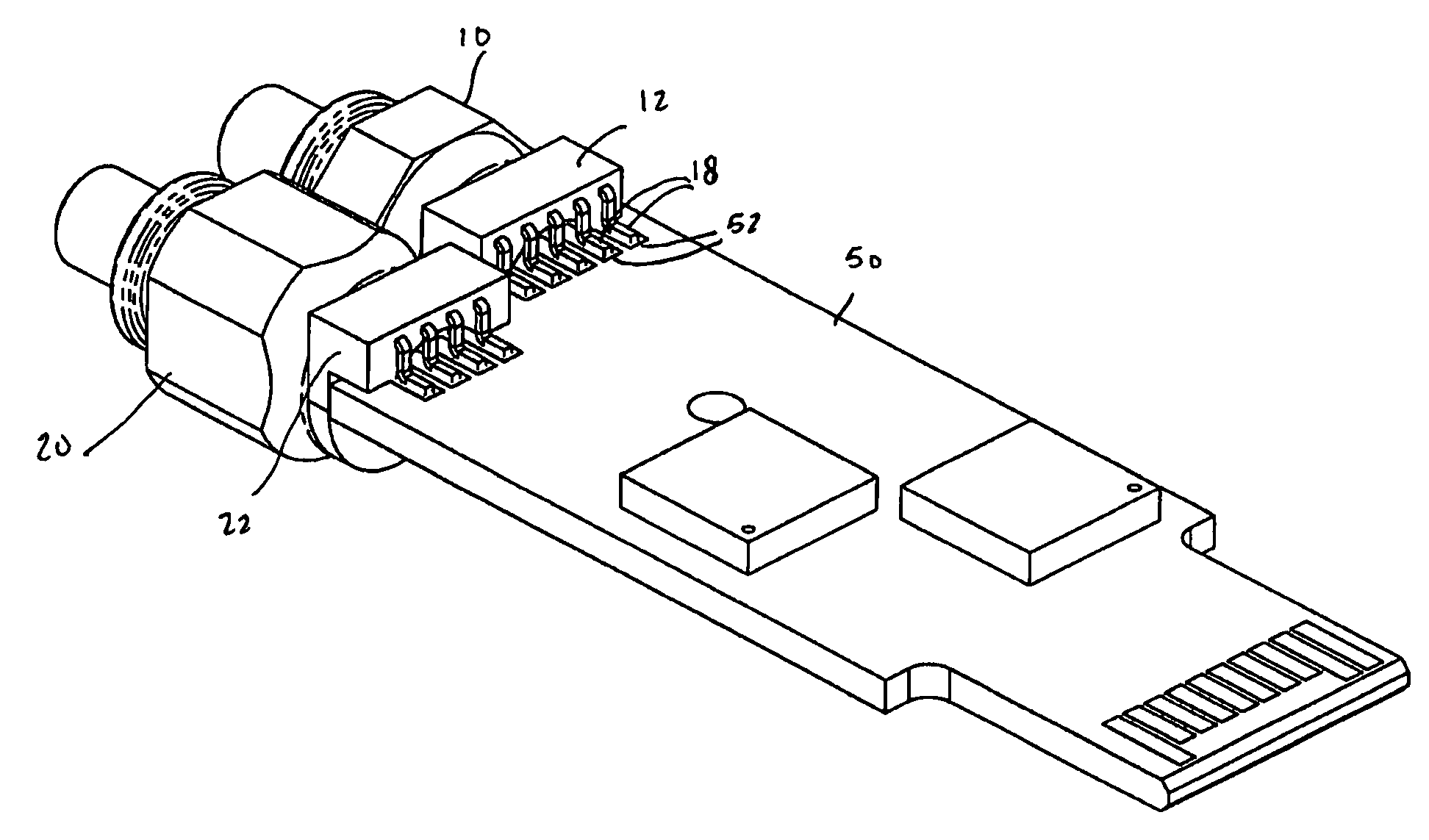
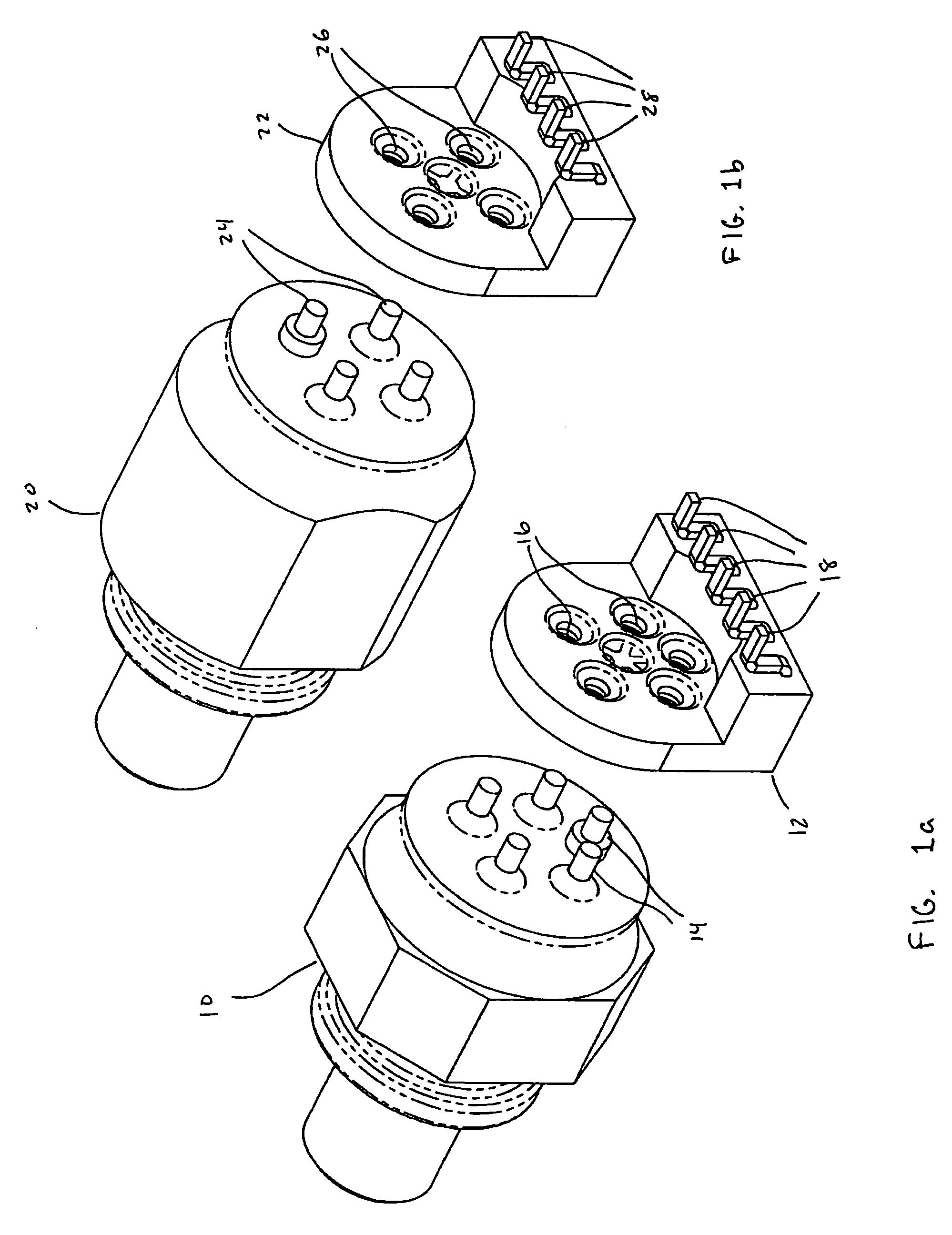
[0011] The present invention relates to methods for manufacturing or assembling optical transceiver modules using lead frame connectors that electrically and mechanically connect optical sub-assemblies to printed circuit boards. The lead frame connectors enable optical sub-assemblies to be connected to the printed circuit board in optical transceiver modules in a reliable and inexpensive manner. The use of such lead frame connectors eliminates the need for flexible printed circuit boards that have been used in conventional transceiver modules.
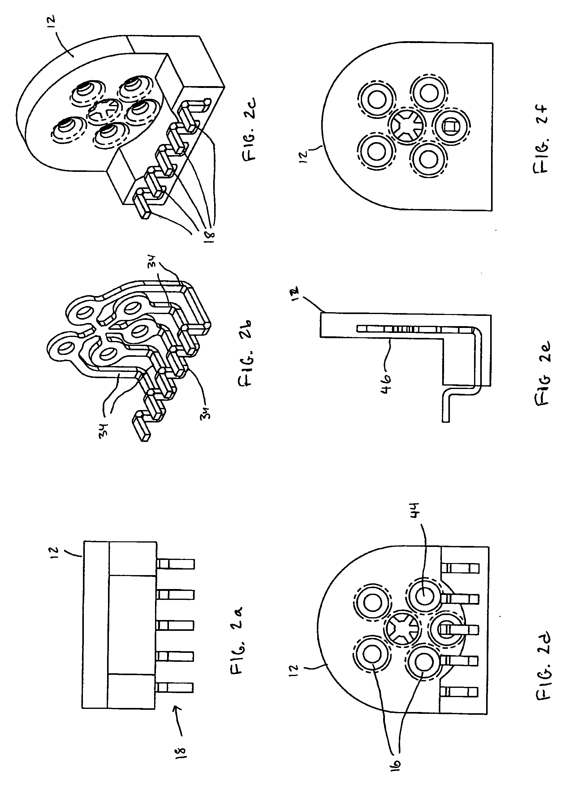
[0012] According to one embodiment, the lead frame connector includes a stamped and bent conductive lead structure that is encased within an insert injection molded plastic casing. The plastic casing provides electrical insulation for the conductors in the lead frame as well as mechanical support for the finished component. The lead frame connectors connect to the leads associated with the optical sub-assemblies. The lead frame connectors also...
PUM
| Property | Measurement | Unit |
|---|---|---|
| Flexibility | aaaaa | aaaaa |
| Electrical conductor | aaaaa | aaaaa |
| Optical properties | aaaaa | aaaaa |
Abstract
Description
Claims
Application Information