Sensor for measuring a tightening force applied on a screw-assembly member

a technology of screw assembly and sensor, which is applied in the direction of screw, load-modified fasteners, instruments, etc., can solve the problems of high manufacturing cost and relatively large electricity consumption, and achieve the effect of optimizing energy consumption and low manufacturing cos

Active Publication Date: 2020-11-10
CENT TECHN DES IND MECANIQUES
View PDF10 Cites 0 Cited by
  • Summary
  • Abstract
  • Description
  • Claims
  • Application Information

AI Technical Summary

Benefits of technology

[0009]Consequently, there exists need for a sensor for measuring a tightening force, making it possible to measure the tightening force applied by a tightening tool to a screw-assembly member while detecting the distancing of the point of application of the tightening force from the main tightening axis, and which has a relatively low manufacturing cost and allows its energy consumption to be optimized.
[0016]Thus, it is possible to measure a tightening force applied by a power tool, for example a screwing device, to a screw-assembly member, by simultaneously measuring the tightening intensity applied in the main screwing axis, but also the distancing of the tightening force along two axes perpendicular to the main screwing axis, so as to be able to refine the measured value of the tightening force. This solution thus makes it possible to obtain all these measurements by installing the strain gauges on a planar and rigid support. Such a solution thus makes it possible to reduce the manufacturing costs of the sensor and improves its electrical consumption.
[0017]Advantageously, and in a nonlimiting manner, the first circuit comprises a full-bridge assembly of strain gauges. Thus, the tightening force in the main tightening axis can be determined in a relatively reliable and inexpensive manner.
[0023]Advantageously, and in a nonlimiting manner, the first gauge of the half-bridge assembly of gauges of the second circuit is installed on an opposite edge of the support strip to the first gauge of the half-bridge assembly of gauges of the third circuit. Thus, the distribution of the gauges on the support strip is optimized, thereby improving the measurements, since it is then possible to determine more finely the deformations of the ring of the sensor.
[0025]Advantageously, the second direction extends along an axis forming a base ortho-normal with an axis in which the first direction extends and with an axis in which the main tightening direction extends. Thus, it is possible to measure the offsetting of a tightening force in two directions perpendicular to the main tightening axis, along two axes, in particular forming a base ortho-normal with the main tightening axis, thereby making it possible to detect all the possible offsettings of the tightening force with respect to the tightening direction.
[0026]The invention also relates to a method for measuring a tightening force applied against a face of a sensor as described above during the tightening of a screw-assembly member passing through the opening of the sensor, comprising a calibration step during which a plurality of forces are successively applied to at least one of the two parallel faces of the sensor, and during which the signals generated by the first circuit, the second circuit and the third circuit are measured so as to determine parameters making it possible to estimate the values of the forces applied against the face of the sensor and the distance of these forces with respect to the center of the opening of the sensor, and a step of measuring the applied tightening force as a function of the signals generated by the three circuits and of the parameters determined during the calibration step.

Problems solved by technology

However, the point of application of the tightening force on the ring is not always in the main tightening axis, in particular in the main axis of screwing for screw assemblies.
However, this type of solution is associated with a relatively high manufacturing cost and with a relatively large electricity consumption.

Method used


Image

  • Sensor for measuring a tightening force applied on a screw-assembly member
  • Sensor for measuring a tightening force applied on a screw-assembly member

Examples


Embodiment Construction

[0032]FIGS. 1 to 4, referring to one and the same embodiment, will be discussed simultaneously.

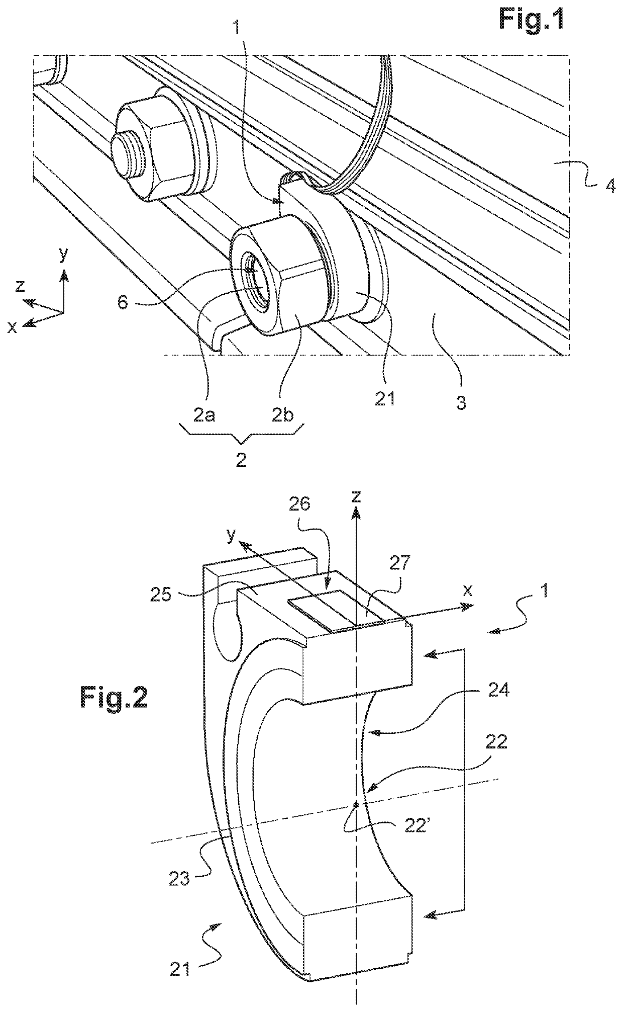
[0033]A sensor 1 makes it possible to measure a tightening force applied to a screw-assembly member 2.

[0034]Here, the screw-assembly member 2 comprises a threaded rod 2a on which a nut 2b is screwed.

[0035]In this embodiment, the threaded rod 2a is coupled to a railway rail 4. For example, a nut (not shown) is screwed onto a free end of the threaded rod 2a so as to be able to retain the threaded rod in abutment against the rail 4 while another nut 2b is being tightened at another free end.

[0036]The threaded rod 2a passes through a fishplate 3 installed against an edge of the rail 4 and receives at the other free end 6 a nut 2b in respect of which it is desired to measure a tightening force.

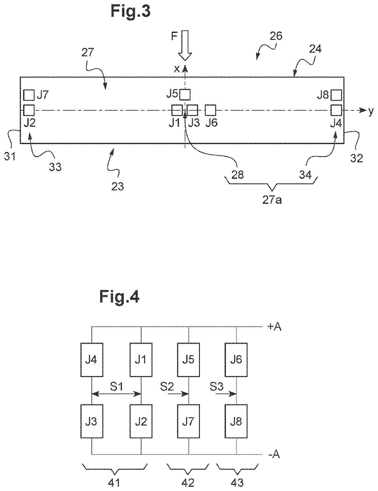
[0037]The sensor 1 comprises a ring 21 fitted over the threaded rod 2a and having an orifice 22 of substantially circular shape. In this embodiment the orifice 22 has a diameter of 28 mm, but it can have ...


PUM

PropertyMeasurementUnit
diameteraaaaaaaaaa
tightening forceaaaaaaaaaa
distanceaaaaaaaaaa

Abstract

A sensor (1) for measuring a tightening force applied on a screw-assembly member (2). The measurement sensor includes a ring and an electronic device comprising a longitudinal support strip having two opposite ends. The support strip is installed on a flat surface of the ring. The electronic device (26) includes a first circuit capable of generating a signal representative of a tightening force applied in a tightening direction on one of the two opposing faces; a second circuit capable of generating a signal representative of the distance of the applied force from the center of the ring in a first direction perpendicular to the tightening direction; and a third circuit capable of generating another signal representative of the distance of the applied force from the center of the ring in a second direction perpendicular to the tightening direction.

Description

CROSS-REFERENCE TO RELATED APPLICATIONS[0001]The present application is a 35 U.S.C. §§ 371 national phase conversion of PCT / FR2017 / 051317, filed May 26, 2017, which claims priority of French Patent Application No. 1654719, filed May 26, 2016, the contents of which are incorporated by reference herein. The PCT International Application was published in the French language.BACKGROUND OF THE INVENTION[0002]The present invention relates to a sensor for measuring a tightening force applied on a screw-assembly member.[0003]Particularly in the railway field, the importance of fixing railway fishplates requires precision control of the tightening forces applied during the fixing thereof to a pair of rails.[0004]When it is desired to know the intensity of a tightening force applied by a power tool, for example an electric screwing device, on a screw assembly, it is known practice to use tightening force sensors.[0005]These force sensors, also referred to as load cells, are installed in such ...

Claims


Application Information

Patent Timeline
Patent Type & Authority Patents(United States)
IPC IPC(8): G01L5/00G01L5/161F16B31/02G01L5/24
CPCG01L5/243F16B31/028G01L5/161G01L5/1627
Inventor ANTHOINE-MILHOMME, DIDIER
Owner CENT TECHN DES IND MECANIQUES
Why Eureka
Try Eureka