Switching power supply apparatus including a plurality of outputs

a power supply apparatus and output technology, applied in the direction of electric variable regulation, process and machine control, instruments, etc., can solve the problems of low accuracy of output voltage stabilization on the non-control output side, output difference between two outputs, and difficulty in high-quality output voltage output, so as to increase the controllable load range, keep the accuracy of output voltage high, and maintain the accuracy of respective output voltages.

Inactive Publication Date: 2015-06-30
MURATA MFG CO LTD
View PDF61 Cites 7 Cited by
  • Summary
  • Abstract
  • Description
  • Claims
  • Application Information

AI Technical Summary

Benefits of technology

[0008]Preferred embodiments of the present invention provide a switching power supply apparatus capable of controlling two outputs with high accuracy at the same time.
[0019]According to various preferred embodiments of the present invention, regardless of variations in magnitudes of loads connected to two outputs, accuracy of respective output voltages are kept high. Moreover, even when an output difference between the two outputs is large, such as when one output is under a light load or no load, accuracy of the output voltages is kept high, and a controllable load range is increased.

Problems solved by technology

However, the output voltage is not determined only depending on a turn ratio of the windings of the transformer because the output voltage is further affected by the presence of influences such as the coupling degree of the transformer, a resistance component, a forward drop voltage across a diode, and surges with switching operations.
In other words, there has been a problem that accuracy in stabilization of the voltage on the non-control output side is low.
In particular, it has been difficult to output the voltage with high accuracy when an output difference between two outputs is large, such as when one output is under a light load or no load.

Method used


Image

  • Switching power supply apparatus including a plurality of outputs
  • Switching power supply apparatus including a plurality of outputs
  • Switching power supply apparatus including a plurality of outputs

Examples


first preferred embodiment

[0036]A switching power supply apparatus according to a first preferred embodiment of the present invention will be described below with reference to FIGS. 2 to 8.

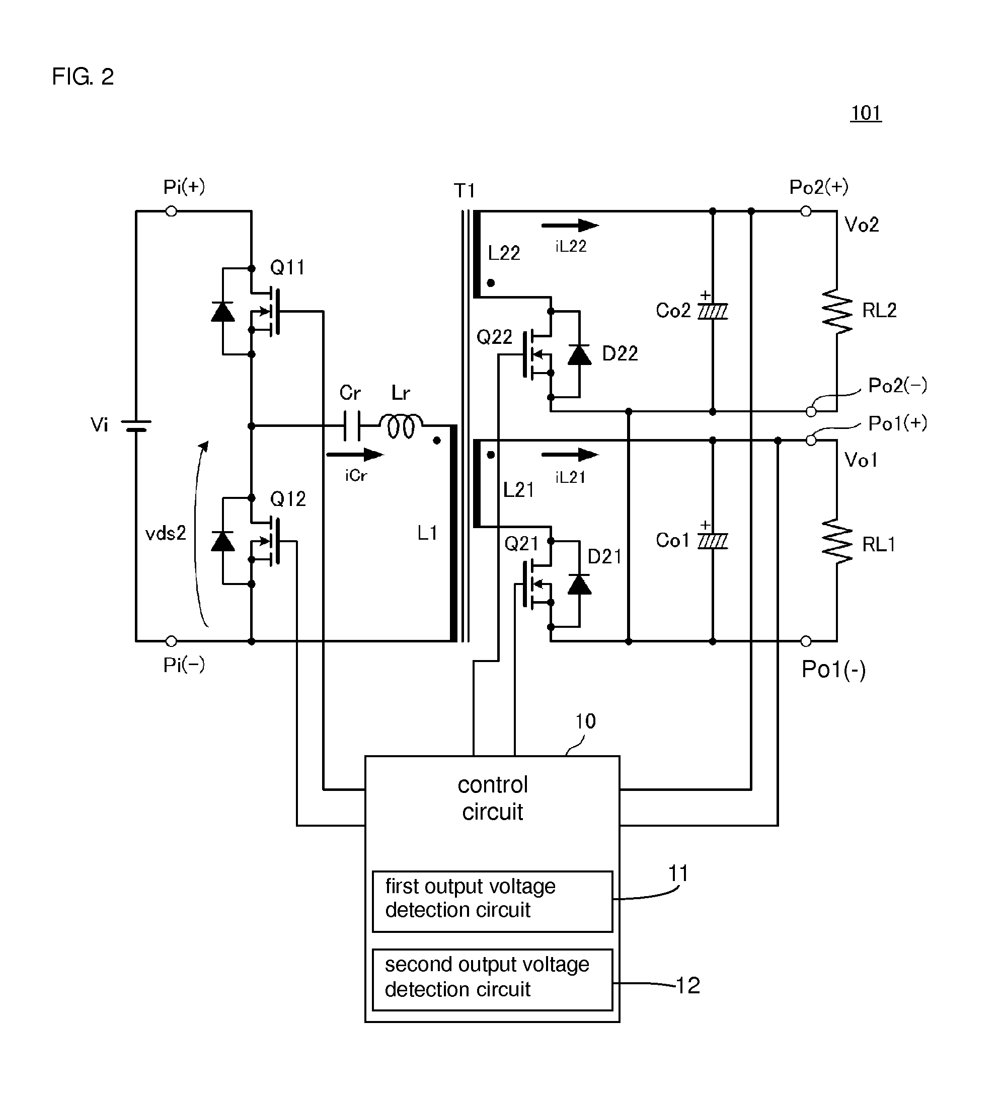
[0037]FIG. 2 is a circuit diagram of a switching power supply apparatus 101 according to the first preferred embodiment. The switching power supply apparatus 101 includes a transformer T1 in which a primary winding L1 is magnetically coupled to a first secondary winding L21 and a second secondary winding L22. A first switching element Q11 and a second switching element Q12 are connected in series between power supply input terminals Pi(+) and Pi(−) both constituting a power supply input portion to which a DC input voltage Vi is input. Between the primary winding L1 of the transformer T1 and the second switching element Q12, a resonant capacitor Cr and an inductor Lr are connected in series to constitute a serial resonance circuit in cooperation with the primary winding L1. The inductor Lr may be constituted in the composit...

second preferred embodiment

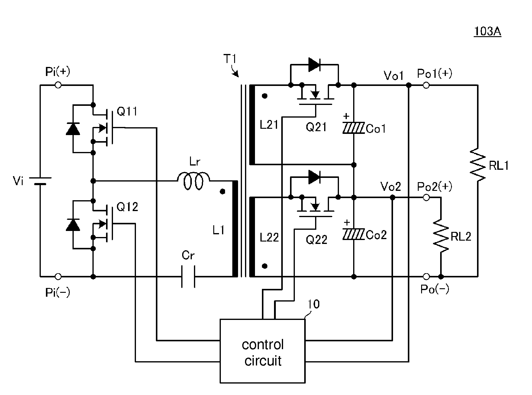
[0091]FIGS. 9A and 9B are circuit diagrams of switching power supply apparatuses 103A and 103B according to a second preferred embodiment of the present invention. The circuit diagram of the second preferred embodiment differs from that of the first preferred embodiment, illustrated in FIG. 2, in the configuration on the secondary side of the transformer T1. The operation of the converter is the same as that in the switching power supply apparatus 101 illustrated in FIG. 2.

[0092]In examples of FIG. 9A, the first secondary winding L21 and the second secondary winding L22 are wound independently of each other, and the grounded side of the first rectifying and smoothing circuit is connected to the voltage output side of the second rectifying and smoothing circuit

[0093]With such a configuration, sharing between the first secondary winding L21 and the second secondary winding L22 is adjusted in supplying electric power. For example, in the case of needing the outputs of Vo1=12 [V], 100 [...

third preferred embodiment

[0097]While each of the above-described preferred embodiments preferably includes a transformer including two secondary windings, a third preferred embodiment includes one secondary winding to provide two output voltages. FIGS. 10 to 13 are circuit diagrams on the secondary side of four switching power supply circuits according to the third preferred embodiment. The configuration on the primary side may be any of the circuits described in the foregoing preferred embodiments.

[0098]In an example of FIG. 10, a voltage doubler rectifier circuit including the rectifier switching elements Q21 and Q22 and the capacitors Co1 and Co2 is associated with a secondary winding L2 of the transformer. During a period in which a positive voltage is generated in the secondary winding L2 on the side denoted by a dot mark, the capacitor Co1 is charged through a path denoted by a solid-line arrow in FIG. 10. During a period in which a negative voltage is generated in the secondary winding L2 on the side...


PUM


Abstract

A resonant capacitor and an inductor are connected in series between a primary winding of a transformer and a second switching element. A first rectifying and smoothing circuit including a first rectifier switching element and a capacitor rectifies and smoothes a voltage generated in a first secondary winding of the transformer, and takes out a first output voltage. A second rectifying and smoothing circuit including a second rectifier switching element and a capacitor rectifies and smoothes a voltage generated in a second secondary winding of the transformer, and takes out a second output voltage. A control circuit controls an on-time of a first switching element and an on-time of the second switching element in accordance with the first output voltage and the second output voltage, respectively.

Description

BACKGROUND OF THE INVENTION[0001]1. Field of the Invention[0002]The present invention relates to a switching power supply apparatus including a plurality of outputs, and more particularly to a switching power supply apparatus capable of controlling two outputs with high accuracy at the same time.[0003]2. Description of the Related Art[0004]For example, Japanese Unexamined Utility Model Registration Application Publication No. 4-121181 and Japanese Unexamined Patent Application Publication No. 6-303771 disclose switching power supply apparatuses each having a plurality of outputs.[0005]Japanese Unexamined Utility Model Registration Application Publication No. 4-121181 discloses a power supply circuit including two secondary windings of a transformer, and a rectifying and smoothing circuit provided for each of the two secondary windings, wherein an output voltage of one of the secondary windings is detected to perform feedback control.[0006]Japanese Unexamined Patent Application Publi...

Claims


Application Information

Patent Timeline
Patent Type & Authority Patents(United States)
IPC IPC(8): H02M3/335H02M3/337H02M1/00
CPCH02M3/33561H02M3/337Y02B70/1433H02M2001/0058Y02B70/1491Y02B70/10H02M1/0058H02M3/33573H02M3/01H02M3/33571
Inventor UNO, YOSHIYUKI
Owner MURATA MFG CO LTD
Why Eureka
Try Eureka