Drive unit for a vehicle wheel

a technology for driving units and wheels, applied in the direction of electric propulsion mounting, rider propulsion, mechanical equipment, etc., can solve the problems of limited application range, difficult to achieve sport-oriented drives, and substantial weight, and achieve the effect of accurate engagement of the toothed drive pinion with the gear ring, convenient housing, and superiority over the wheel hub driv

Active Publication Date: 2015-10-20
LANG GUENTER
View PDF15 Cites 24 Cited by
  • Summary
  • Abstract
  • Description
  • Claims
  • Application Information

AI Technical Summary

Benefits of technology

[0011]With the drive unit according to the invention, the motor carrier is movably supported by one or several guide wheels on the guide profile whereby an accurate engagement of the toothed drive pinion with the gear ring is ensured. This greatly facilitates on one hand the installation of the gear ring and the guide profile on the wheel and, on the other hand, the attachment of the motor carrier to the frame.
[0012]The position of the motor carrier is determined by the guide profile. If the drive wheel has been mounted with a slight eccentricity error or a sideward displacement, the motor carrier can follow the profile path without detrimentally affecting the engagement conditions between the drive pinion and the gear ring. Also dynamic deformation-caused (for example load-based) changes of the distances between wheel and frame parts can be easily accommodated in this way. As a result, the drive unit according to the invention is particularly suitable in sport-based applications such as, for example, mountain bikes without involving any limitations.
[0013]Furthermore, the drive unit according to the invention may be used in connection with bicycles with un-spring frames as well as with spring frames. The motor carrier is attached to the vehicle frame wherein “frame” includes also movable parts, spring supported parts, as well as rigidly mounted parts, as for example, a resiliently or a rigidly supported fork or a rear wheel pivot arm. By the use of the drive unit for driving the rear wheel and its connection to a spring support arm, a further advantage over a wheel hub drive is obtained. Even if the motor carrier including the motor has the same weight as a conventional wheel hub drive, the electric motor may be arranged closer to the pivot center (pivot arm bearing) of the rear wheel pivot arm as this is possible with a wheel hub motor. As a result, the unsprung mass effective at the rear wheel axis is reduced. The effect is substantial because of the square connection between the mass inertia moment and the distance of the center point of gravity of the un-spring mass from the center of rotation.
[0014]The drive unit according to the invention can easily be retrofitted and is self-guided since the motor carrier including the electric motor, the drive pinion and the guide wheel or wheels roll on the guide profile ring on which the wheels are guided. The guide profiles are formed by guide tracks on which the motor unit rolls along. To this end, the motor unit is relatively movably supported with respect to the vehicle frame. The movable support arrangement serves preferably only for the support of the drive moment.
[0017]Preferably, the drive connection between the electric motor and the gear ring can be separated as desired, for example, by disengaging the drive pinion gear from the gear ring, for example, by axial shifting of the drive pinion gear out of the gear ring or by opening a coupling or clutch provided for that purpose. In this way, the bike can be operated selectively without electric motor support or braking. This is desirable, in particular, for sport-oriented bikes, for example, when they wish to drive uphill without motor support, or when a cyclist has run out of battery power. Also, in this way, the braking effect of the drive unit can be eliminated on downhill stretches which however otherwise could be utilized for energy recuperation.

Problems solved by technology

Although wheel hub drives are a common solution for the implementations of an auxiliary drive or possibly also a main drive, they have a substantial weight and they require either an exchange or a re-spoking of the wheel which is to be provided with a drive unit.
They are therefore not particularly suitable for retro-fitting.
In particular, a combination of a hub motor with a chain gear shift mechanism as it is provided generally with sporty bikes and which is favored by sport-oriented drives is difficult and possible only within limits.
Especially sport-oriented drivers often own valuable bikes which do not lend themselves to an installation of wheel hub drives of any type.
The driver may also find it objectionable that the electric auxiliary drive prevents the wheel from rotating freely when the motor is not energized that is when the motor runs neither as motor nor as generator.

Method used


Image

  • Drive unit for a vehicle wheel
  • Drive unit for a vehicle wheel
  • Drive unit for a vehicle wheel

Examples


Embodiment Construction

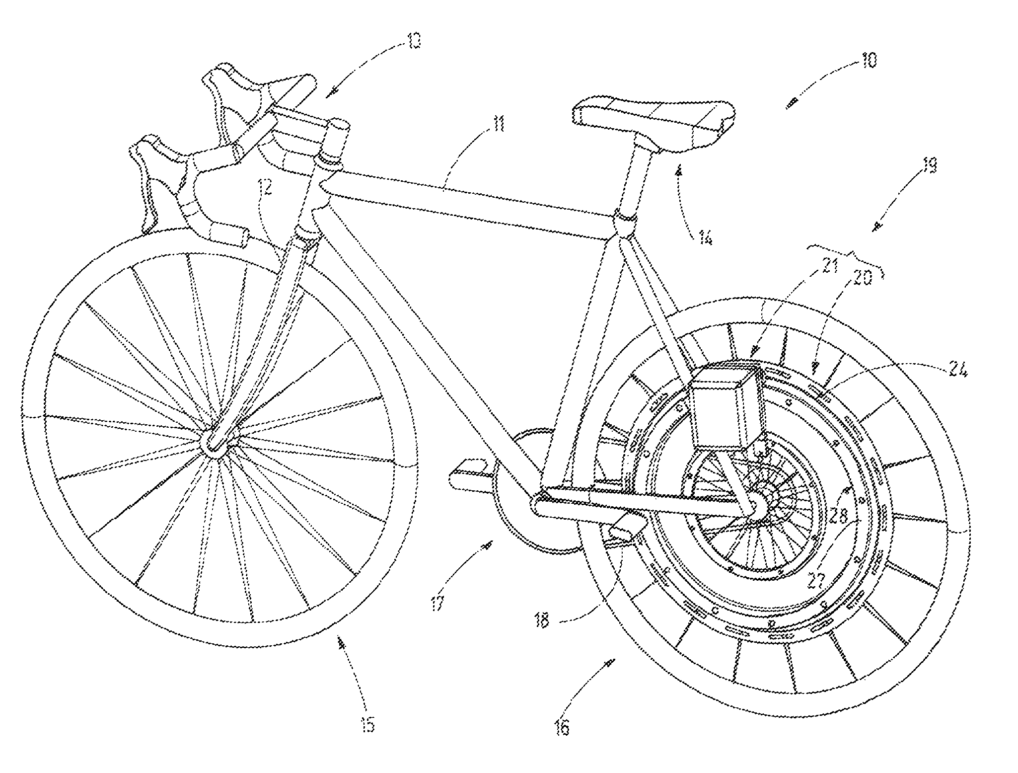
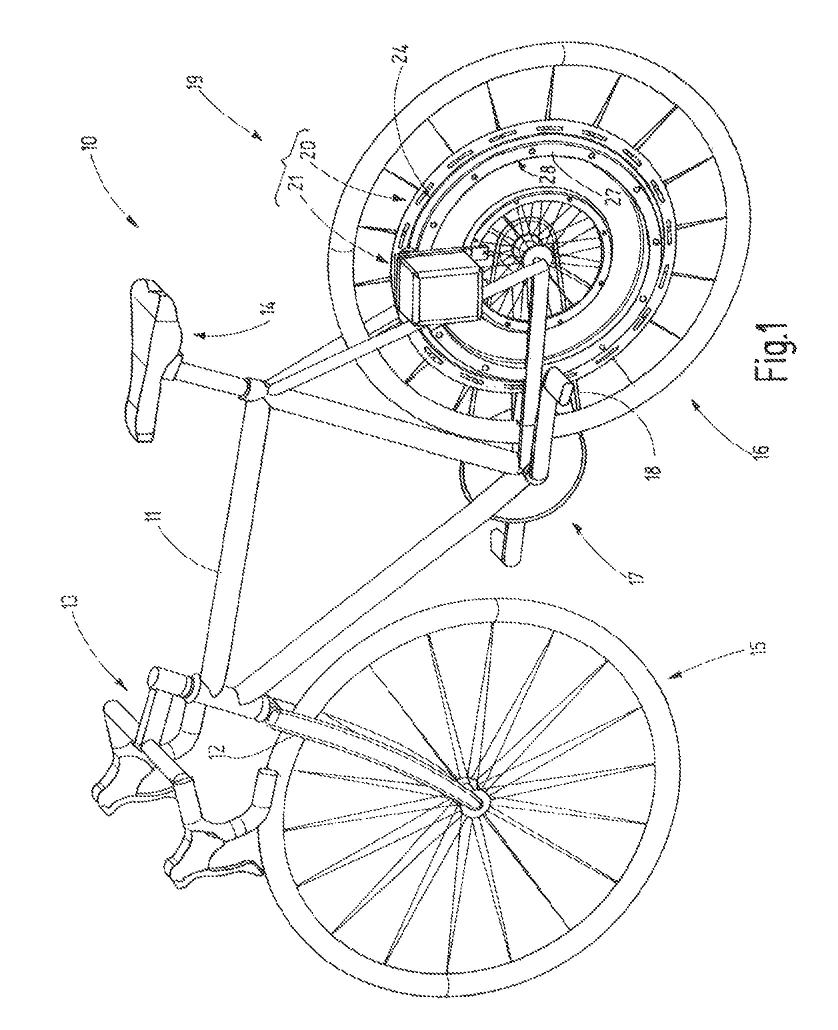
[0032]FIG. 1 shows a bike 10 which has the usual components, namely a frame 11, a fork 12, a handle bar 13, a seat 14, as well as, front wheel 15 and a rear wheel 16. For operator operation, a crank 17 is provided by which, via a chain 18 the rear wheel 16 can be driven. Preferable the bike 10 includes a gear shift transmission, which is not shown, preferably in the form of a chain gear shifter. However, it may also have a hub gear shifter which may be disposed in the rear wheel hub and / or the crank 17.

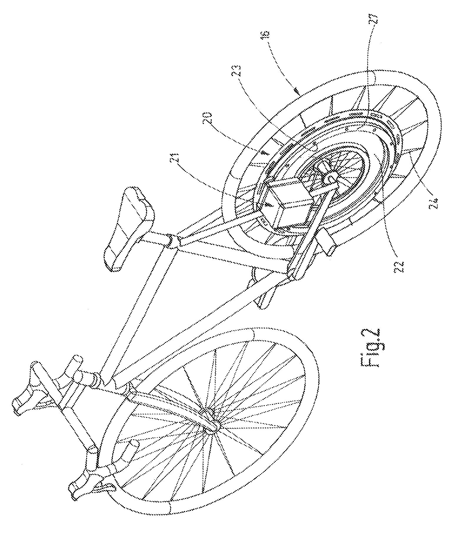
[0033]The front wheel 15 and / or the rear wheel 16 is provided with a drive unit 19 according to the present invention which may be in the form of an auxiliary drive or, if desired, as the main drive. That is that, it can be used at times or always as the sole drive. The drive unit 19 is an electric drive. An associated energy storage device is not shown in FIG. 1. This may be a suitable battery pack, such as, for example, a lithium-run battery or similar. In addition, the respective e...


PUM


Abstract

The drive unit (19) according to the invention for light vehicles, in particular bicycles, comprises a wheel unit (20) and a motor unit (21). The wheel unit (20) includes a gear ring (27) and at least one, preferably two support tracks (31, 35) on which the motor unit (21), which is movably supported but circumferentially fixed to the frame (11), runs. In this way, a wheel-support arrangement for the motor unit (21) is provided. As a result, also with extreme light-weight designs as used in connection with bicycles even in sport applications, a correct engagement between the wheel mounted gear ring (27) and drive pinion (45) is achieved.

Description

CROSS-REFERENCE TO RELATED APPLICATION[0001]This is a continuation-in-part application of pending international application PCT / EP2011 / 065685 filed Sep. 9, 2011 and claiming the priority of German Application No. 10 2010 037 435.0 filed Sep. 9, 2010.BACKGROUND OF THE INVENTION[0002]The invention resides in a drive unit for a wheel or wheels of a vehicle which is operated at least partially by an electric motor.[0003]DE 20 2009 014 347 U1 discloses, for example, a bicycle which, in addition to the pedal crank drive, is provided with an electric motor which drives the rear wheel and which supports the pedal power of the driver. The electric motor is disposed in the rear wheel hub.[0004]Also, DE 602 09 510 T2 which is mainly concerned with the control of an electric motor or a bicycle favors a wheel hub drive.[0005]Although wheel hub drives are a common solution for the implementations of an auxiliary drive or possibly also a main drive, they have a substantial weight and they require ...

Claims


Application Information

Patent Timeline
Patent Type & Authority Patents(United States)
IPC IPC(8): B60K1/00B62M6/75
CPCB60K1/00B62M6/75Y10T74/19684
Inventor LANG, GUENTER
Owner LANG GUENTER
Why Eureka
Try Eureka