Pressure control valve arrangement having a pressure medium channel of oval cross-section

a technology of pressure control valve and pressure medium channel, which is applied in the direction of application and release valve, braking system, braking components, etc., can solve the problem of relative large flow loss

Active Publication Date: 2015-11-10
KNORR-BREMSE SYST FUER NUTZFAHRZEUGE GMBH
View PDF23 Cites 4 Cited by
  • Summary
  • Abstract
  • Description
  • Claims
  • Application Information

AI Technical Summary

Benefits of technology

[0011]As a result, the pressure medium duct is of narrower construction measured across its flow cross section perpendicular to the plane comprising the central axis, which is advantageous with regard to the restricted installation space of such pressure control valve arrangements. It is therefore also possible for multiple such pressure medium ducts to be arranged with their minor dimension b in each case adjacent to one another without the dimensions of the pressure control valve arrangement in the direction becoming too large, or the diameter of adjacent pressure medium ducts can be made larger.
[0013]The flow-guiding or flow-diverting pressure medium guiding surface, which may be of knee-like configuration, of the pressure medium duct at the diversion of the flow from the portion leading in one direction into the portion leading in the other direction may then be configured such that the flow losses or flow resistances arising in the pressure medium duct are reduced.
[0014]Owing to the reduced flow resistance, improved dynamics of the pressure control valve arrangement are consequently obtained with an unchanged flow cross section of the pressure medium duct in question, which has a positive effect with regard to the demanded fast succession of pressure dissipation, pressure holding and pressure increasing phases.

Problems solved by technology

A problem from a flow aspect is a resulting diversion of a pressure medium duct, because the diversion takes place abruptly in the intersection region between the vertical bore and the horizontal bore, and relatively large flow losses arise as a result of the abrupt diversion.

Method used


Image

  • Pressure control valve arrangement having a pressure medium channel of oval cross-section
  • Pressure control valve arrangement having a pressure medium channel of oval cross-section
  • Pressure control valve arrangement having a pressure medium channel of oval cross-section

Examples


Embodiment Construction

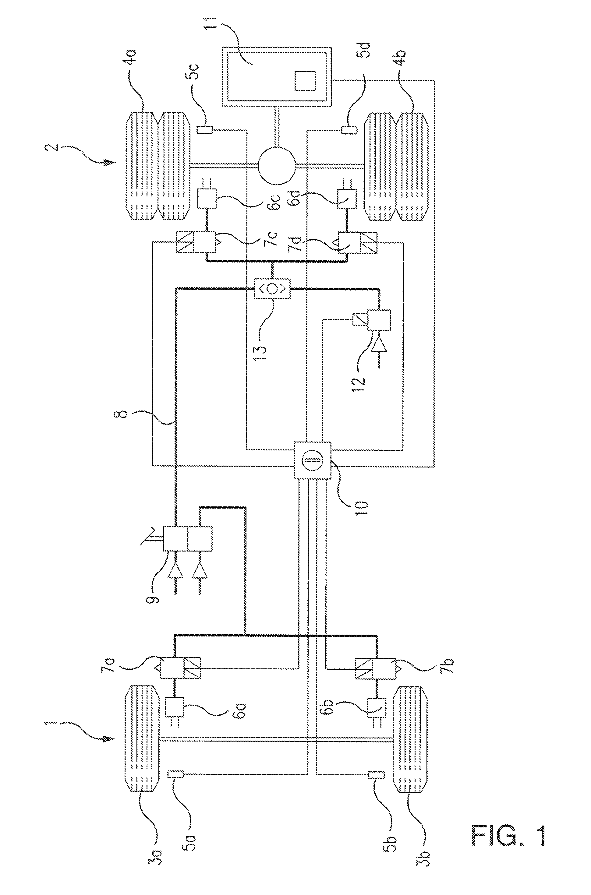
[0025]According to FIG. 1, a vehicle equipped with an ABS brake system has a front axle 1 and a rear axle 2. Arranged on the front axle 1 are wheels 3a and 3b; the rear axle 2 has for example wheels 4a and 4b each with twin tires. The ABS brake system used for braking the wheels 3a, 3b and 4a, 4b is configured here in the form of a 4S / 4C system (four sensors, four channels). This means that, here, a total of four rotational speed sensors 5a-5d and four pressure control valve arrangements 7a-7d are provided. The pressure control valve arrangements 7a-7d serve for actuating respectively associated brake cylinders 6a-6d. All of the pressure control valve arrangements 7a-7d are connected via a branching pneumatic brake pressure line 8 to a foot brake valve 9.

[0026]The driver, when actuating the foot brake valve 9, generates a brake pressure which is transmitted via the pneumatic brake pressure line 8 through the pressure control valve arrangements 7a-7d to the brake cylinders 6a-6d assi...


PUM


Abstract

A pressure control valve arrangement is described for controlling a fluid pressure in an ABS brake system of a vehicle such that, in the event of a tendency of individual wheels of the vehicle to lock, the brake pressure in at least one associated brake cylinder can be adaptively adjusted, including: a housing in which is formed at least one pressure-medium-conducting pressure medium duct and in which is provided a diversion of the flow of the pressure medium within the pressure medium duct from a portion of the pressure medium duct leading in one direction into a portion of the pressure medium duct leading in another direction, in which the pressure medium duct is produced together with the housing by primary forming, and in which the cross section of the pressure medium duct is oval and the major dimension of the oval cross section and the central axis of the pressure medium duct are arranged in a common plane, and the minor dimension of the oval cross section is perpendicular to the plane.

Description

FIELD OF THE INVENTION[0001]The present invention relates to a pressure control valve arrangement for controlling the fluid pressure in an ABS brake system of a vehicle such that, in the event of a tendency of individual wheels of the vehicle to lock, the brake pressure in at least one associated brake cylinder can be adaptively adjusted, wherein in a housing of the pressure control valve arrangement there is formed at least one pressure-medium-conducting pressure medium duct and there is provided a diversion of the flow of the pressure medium within the pressure medium duct from a portion of the pressure medium duct leading in one direction into a portion of the pressure medium duct leading in another direction, as per the description herein.BACKGROUND INFORMATION[0002]ABS (anti-lock braking systems) prevent the wheels from locking, and perform their function if greater traction is demanded between a tire and the roadway than can be transmitted, that is to say if the driver overbra...

Claims


Application Information

Patent Timeline
Patent Type & Authority Patents(United States)
IPC IPC(8): B60T8/36B60T8/48B60T8/88
CPCB60T8/3605B60T8/4818B60T8/885
Inventor GREBE, JANBRENNER, DIRKWEIPPERT, JOCHENROHN, WOLFGANGJAEHNS, HARALD
Owner KNORR-BREMSE SYST FUER NUTZFAHRZEUGE GMBH
Why Eureka
Try Eureka