Triangulation system for flat machine

A cam system and cam technology, applied in the field of cam systems used in flat knitting machines, can solve problems such as the inability to use the cam parts of the needle cam, achieve the effects of shortening knitting time, shortening adjustment time, and improving operational reliability

Active Publication Date: 2011-11-09
KARL MAYER STOLL R&D GMBH
View PDF6 Cites 4 Cited by
  • Summary
  • Abstract
  • Description
  • Claims
  • Application Information

AI Technical Summary

Problems solved by technology

However, it is not currently possible to use the triangular part on the needle cam to adjust the protruding position of the knitting needle according to the pattern to be knitted or the yarn used

Method used


Image

  • Triangulation system for flat machine
  • Triangulation system for flat machine
  • Triangulation system for flat machine

Examples


Embodiment Construction

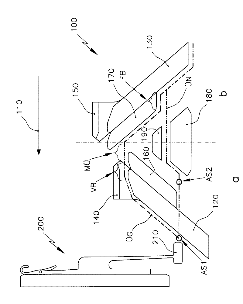
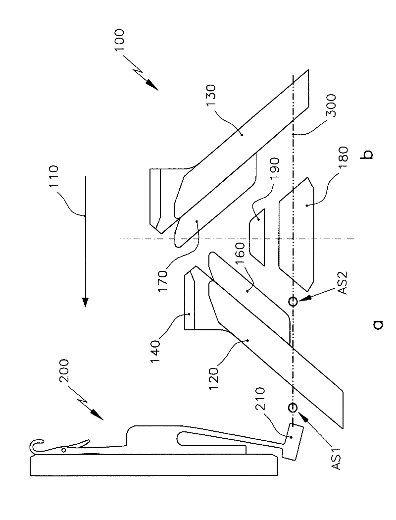
[0027] figure 1 a, 2a, 4a and 5a are schematic illustrations of a knitting needle 200 having a drive foot 210 arranged at its end, which is arranged on an elastic section 220 of a needle shank 230 so as to be pivotably limited. The needles 200 are located in the needle bed 250 . The illustrated needle 200 is exemplary only. It is also possible to use the needle cam shown in the figures to actuate other needle configurations with drive feet that are translatable between a position that is lowered into the needle bed and a position that is raised above the needle bed.

[0028] exist figure 1 In a, the driving foot 210 of the knitting needle 200 is not touched. In this state, the driving foot does not protrude from the needle bar 230, and thus cannot be connected with the figure 1 The needle cam 100 shown in b is engaged. The drive foot 210 thus passes the needle cam 100 during its movement along the horizontally extending line 300 indicated by the dotted line in the directi...


PUM


Abstract

Provided is a triangulation system for a flat machine, comprising at least a needle triangle (100) which is structured to be a combined triangle of looping and a loop transferring. The needle triangle includes two stitch cams (120, 130) which are symmetrically arranged with a line (M) as a center. The inner sides of the stitch cams (120, 130) are provided with additional triangle portions (160, 170) capable of movement and adjustment. The additional triangle portions can adjust the protruding position of knitting needles for looping, loop transferring and / or inlaying.

Description

technical field [0001] The invention relates to a cam system for a flat knitting machine, which has at least one needle cam (Nadelschloss), which is designed as a combined stitch forming and transfer cam, with which needle cam is partially adjustable The triangular part (Schlossteil) of the needle bed produces different channel curves (Durchgangskurve) for the drive feet of the knitting needles arranged in the needle grooves of the needle bed, in order to realize the knitting needles. The function of the loop (Maschenübernahme), the needle cam has two bending cams arranged symmetrically with respect to its center line. Background technique [0002] Such a combined knitting and transfer cam for flat knitting machines is known, for example, from US 4,729,230, which has a plurality of adjustable cam sections located inside the bending cam. With these cam systems, the needles can be advanced and retracted again according to the desired function: loop formation, tuck formation, ...

Claims


Application Information

Patent Timeline
Patent Type & Authority Applications(China)
IPC IPC(8): D04B15/36
CPCD04B15/365
Inventor A.迪博尔德S.迈尔
Owner KARL MAYER STOLL R&D GMBH
Why Eureka
Try Eureka