Fault diagnosis method for power converter of switch reluctance motor

A power converter and fault diagnosis technology, which is applied to the measurement of electrical variables, motor generator testing, instruments, etc., can solve the problems that the system cannot judge the type and location of the fault, and does not have the functions of fault detection and fault location.

Inactive Publication Date: 2009-10-07
CHINA UNIV OF MINING & TECH
View PDF0 Cites 43 Cited by
  • Summary
  • Abstract
  • Description
  • Claims
  • Application Information

AI Technical Summary

Problems solved by technology

At present, the developed switched reluctance motor system does not have the functions of fault detection and fault location. When the power converter is prone to faults, the system cannot judge the fault type and fault location

Method used


Image

  • Fault diagnosis method for power converter of switch reluctance motor
  • Fault diagnosis method for power converter of switch reluctance motor
  • Fault diagnosis method for power converter of switch reluctance motor

Examples


Embodiment 1

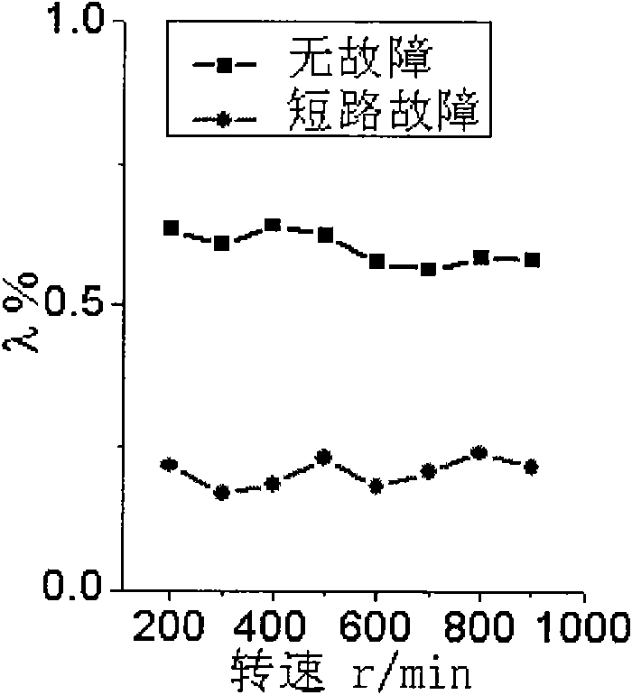
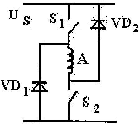
[0023] Embodiment one, figure 2 As shown, taking the asymmetrical half-bridge (double switch) switched reluctance motor power converter as an example, S 1 and S 2 main switch, VD 1 and VD 2 It is a freewheeling diode, and the DC supply voltage is U S . Test the current spectrum of each phase when the power converter of switched reluctance motor is running without fault, and take the relative spectral ratio coefficient of each phase current as the fault characteristic quantity. If the relative spectral ratio coefficient of all phase currents is basically constant and does not change significantly, the power The converter is not faulty. If the amplitudes of the DC component and the fundamental component of the A-phase current are close to zero, an open-circuit fault occurs in the A-phase; compared with the relative spectral ratio coefficient of the A-phase current when no fault occurs, if the relative spectrum The ratio coefficient changes obviously, and the relative spec...

Embodiment 2

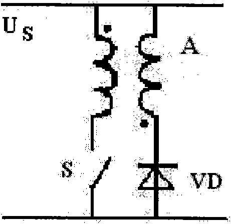
[0027] Embodiment two, image 3 As shown, taking the double-winding switched reluctance motor power converter as an example, S is the main switch, VD is the freewheeling diode, and the DC supply voltage is U S . Test the current spectrum of each phase when the power converter of switched reluctance motor is running without fault, and take the relative spectral ratio coefficient of each phase current as the fault characteristic quantity. If the relative spectral ratio coefficient of all phase currents is basically constant and does not change significantly, the power The converter is not faulty. If the amplitudes of the DC component and the fundamental component of the A-phase current are close to zero, an open-circuit fault occurs in the A-phase; compared with the relative spectral ratio coefficient of the A-phase current when no fault occurs, if the relative spectrum The ratio coefficient changes obviously, and the relative spectrum ratio coefficient of the A-phase current ...

Embodiment 3

[0031] Embodiment three, Figure 4 As shown, taking the capacitive voltage divider switched reluctance motor power converter as an example, S 1 and S 2 main switch, VD 1 and VD 2 It is a freewheeling diode, and the DC supply voltage is U S , C 1 and C 2 is the voltage divider capacitor. Test the current spectrum of each phase when the power converter of switched reluctance motor is running without fault, and take the relative spectral ratio coefficient of each phase current as the fault characteristic quantity. If the relative spectral ratio coefficient of all phase currents is basically constant and does not change significantly, the power The converter is not faulty. If the amplitudes of the DC component and the fundamental component of the A-phase current are close to zero, an open-circuit fault occurs in the A-phase; compared with the relative spectral ratio coefficient of the A-phase current when no fault occurs, if the relative spectrum The ratio coefficient chan...


PUM


Abstract

The invention relates to a fault diagnosis method for a power converter of a switch reluctance motor; current spectrum of the power converter phase of the switch reluctance motor is tested and used asfault characteristic quantity; and the proportion coefficient Lambada of relative spectrums ratio of the phase current is defined as the ratio of the amplitude of fundamental component of the phase current and the amplitude of direct current component of the phase current. If the coefficient of the relative spectrum ratio of all phase current is basically constant, the power converter does not occur fault; if the amplitudes of the direct current component and the fundamental component of a certain phase current are near to zero respectively, the phase occurs open fault; and compared with thecoefficient of the relative spectrum ratio of the phase current without fault, if the coefficient of the relative spectrum ratio of a certain phase current occurs obvious change, the phase occurs short fault. The method not only can be used for fault detection, discrimination for types of faults and positioning of fault phases when one phase of the power converter of the switch reluctance motor occurs fault, but also can be used for fault detection, discrimination for types of faults and positioning of fault phases when two or more than two phases of the power converter of the switch reluctance motor occur fault.

Description

technical field [0001] The invention relates to a fault diagnosis method for a switched reluctance motor power converter, which is especially suitable for switched reluctance motor power converters with various phase numbers and topological structures. Background technique [0002] The switched reluctance motor power converter is a unipolar power converter that supplies unipolar current to the switched reluctance motor. The most common switched reluctance motor power converters include asymmetrical half-bridge (double switch), double-winding, capacitor voltage divider, capacitor dump, common switch, resistor commutation, inductive commutation ( H bridge), etc. Since the switched reluctance motor adopts a simple and strong rotor structure without brush, winding, and permanent magnet, it is easy to make dust-proof and explosion-proof structures, and is very suitable for harsh environments such as high dust, flammability, and explosion. Moreover, the brushless, winding-free, ...

Claims


Application Information

Patent Timeline
Patent Type & Authority Applications(China)
IPC IPC(8): G01R31/34G01R31/02
Inventor 陈昊卢胜利
Owner CHINA UNIV OF MINING & TECH
Why Eureka
Try Eureka