Electric pressure cooker and upper cover assembly of electric pressure cooker

A technology of electric pressure cooker and cover assembly, which is applied to pressure cooker, kitchen utensils, household utensils, etc., which can solve the problems of damaged rotary chuck operation, inconvenient operation of electric pressure cooker, low safety and reliability, etc., to achieve firm installation and improved operation reliability The effect of improving and improving accuracy

Active Publication Date: 2019-03-12
FOSHAN SHUNDE MIDEA ELECTRICAL HEATING APPLIANCES MFG CO LTD +1
View PDF6 Cites 42 Cited by
  • Summary
  • Abstract
  • Description
  • Claims
  • Application Information

AI Technical Summary

Problems solved by technology

[0003] However, for irregular-shaped electric pressure cookers, such as oval pressure cookers, since the shapes of the upper cover, inner pot and outer pot are all oval, the traditional rotary buckle type will be difficult to apply directly here. The lid is separately provided with a fastening piece that fastens the outer pot, and a rotary chuck that pushes the fastening piece to move radially along the pot cover to open or lock the fastening piece through rotary motion, and the rotating chuck slides with the fastening piece through the pillar connect
During the cooking process of the electric pressure cooker, the upper cover and the buckle must bear the steam pressure in the pot. In order to ensure the smoothness and stability of the fastening mechanism, the strength and stiffness at the position of the pillar must be considered. However, the existing technology The support structure on the non-circular electric pressure cooker bears a relatively large force, is easy to be damaged and makes the operation of the rotary chuck difficult, and the electric pressure cooker is inconvenient to operate and has low safety and reliability

Method used


Image

  • Electric pressure cooker and upper cover assembly of electric pressure cooker
  • Electric pressure cooker and upper cover assembly of electric pressure cooker
  • Electric pressure cooker and upper cover assembly of electric pressure cooker

Examples


Embodiment Construction

[0041] Embodiments of the invention are described in detail below, examples of which are illustrated in the accompanying drawings. The embodiments described below by referring to the figures are exemplary and are intended to explain the present invention and should not be construed as limiting the present invention.

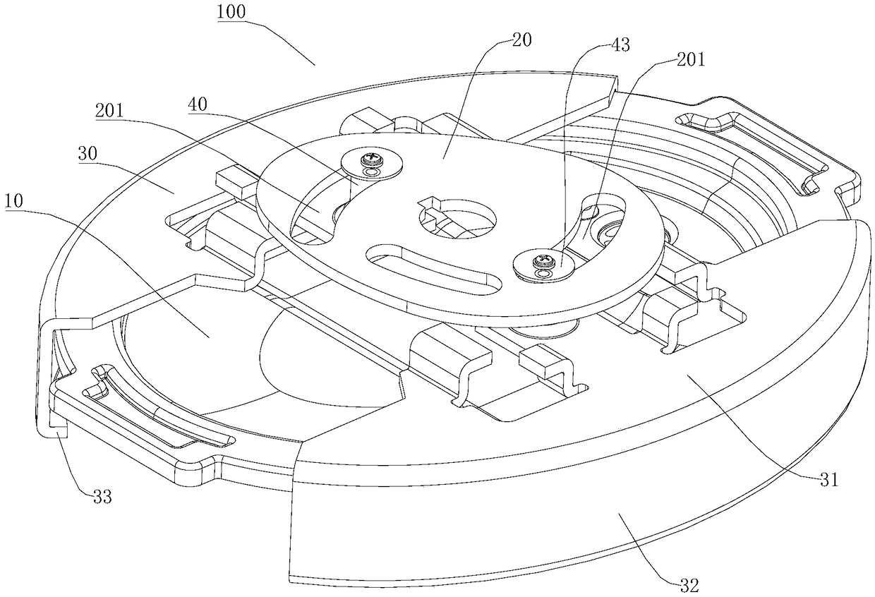
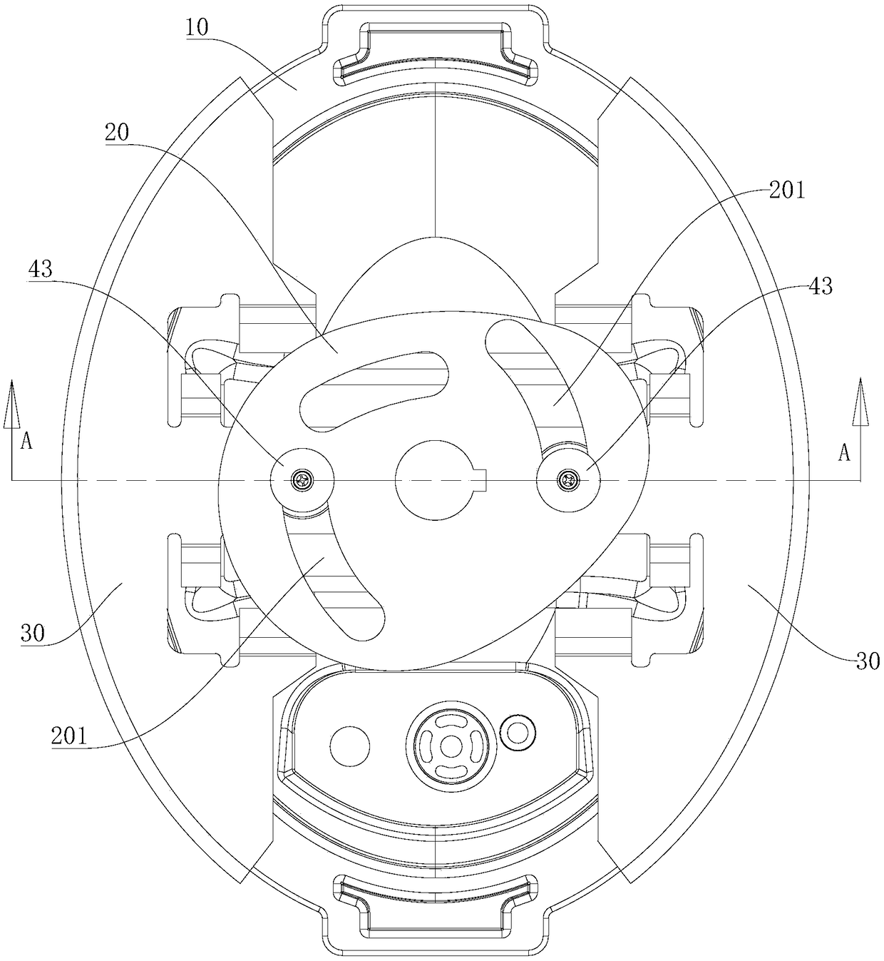
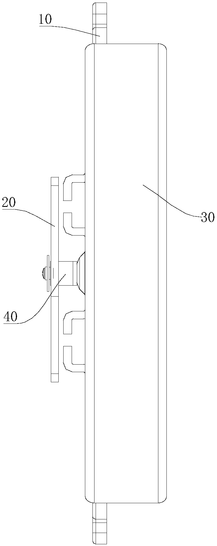
[0042] The upper cover assembly 100 of the electric pressure cooker according to the embodiment of the present invention will be described in detail below with reference to the accompanying drawings.

[0043] refer to Figure 1 to Figure 14 As shown, the upper lid assembly 100 of the electric pressure cooker according to the embodiment of the present invention may include an upper lid body 10 , a rotary chuck 20 , two fastening elements 30 , two pillars 40 and two elastic elements 50 . Of course, the number of snap-fitting parts 30, struts 40 and elastic parts 50 is not limited thereto, and can be set according to specific conditions, but the number of snap-fit ...


PUM


Abstract

The invention discloses an upper cover assembly of an electric pressure cooker and the electric pressure cooker with the upper cover assembly. The upper cover assembly comprises an upper cover body, a rotating chuck, a plurality of fasteners, a plurality of support posts and stop gaskets, wherein the rotating chuck is pivotally connected with the upper cover body; a clamping groove is formed in the rotating chuck; the plurality of support posts are connected with the corresponding fasteners, are matched in the clamping groove, are propped against the clamping groove when the rotating chuck rotates, and move long the radial direction of the rotating chuck to drive the fasteners to be fastened to or separated from an outer pot; the stop gaskets are fixed at the upper ends of the support posts; and the sizes of the stop gaskets are greater than the width of the clamping groove in the width direction of the clamping groove. The upper cover assembly of the electric pressure cooker is good in operation smoothness and high in stability, the support posts are not easy to damage and the service life is relatively long.

Description

technical field [0001] The invention relates to the technical field of kitchen appliances, and more particularly, to an upper cover assembly of an electric pressure cooker and an electric pressure cooker with the upper cover assembly. Background technique [0002] In the related art, the electric pressure cooker includes a pot cover, an outer pot and an inner pot. The pot cover is provided with inner buckle teeth, and the outer pot is provided with outer pot teeth. The outer buckle teeth of the pot are buckled together. When the lid is buckled, by rotating the lid, the inner buckle teeth of the pot cover and the outer buckle teeth of the outer pot are buckled together, so that the lid is sealed with the inner pot through the sealing ring. Combination, when opening or closing the lid, only need to rotate the operation. [0003] However, for irregular-shaped electric pressure cookers, such as oval pressure cookers, since the shapes of the upper cover, inner pot and outer pot ...

Claims


Application Information

Patent Timeline
Patent Type & Authority Patents(China)
IPC IPC(8): A47J27/08
CPCA47J27/08A47J27/0804A47J27/0806
Inventor 梅若愚何柏锋潘典国龚俭龙
Owner FOSHAN SHUNDE MIDEA ELECTRICAL HEATING APPLIANCES MFG CO LTD
Why Eureka
Try Eureka