Test signal generator for low-density parity-check decoder

a low-density parity-check and signal generator technology, applied in the direction of coding theory basic assumptions, code conversion, code conversion, etc., can solve the problems of rare noise in the read channel error due to noise, the np-complete problem of decoding a low-density parity-check code on the binary symmetric channel, and the bad situation of the decoder

Active Publication Date: 2016-03-22
AVAGO TECH INT SALES PTE LTD
View PDF3 Cites 0 Cited by
  • Summary
  • Abstract
  • Description
  • Claims
  • Application Information

AI Technical Summary

Benefits of technology

[0015]In another embodiment of the present invention, an encoder is calibrated according to channel parameters and low-density parity-check code characteristics. Calibration based on a set of simulated results allows the encoder to focus on noise models most likely to produce error events.

Problems solved by technology

Read channel errors due to noise are rare.
It is known that decoding a low-density parity-check code on the binary symmetric channel is an NP-complete problem.
This is a very bad situation for the decoder because the decoder does not have the ability to identify the valid but erroneous word.
The Cole method deals with so-called trapping sets (or near codewords), i.e. Some words, which are not codewords but can be converted to codewords with small effort, and leading to errors in case of small levels of noise.
The second step of the Cole method finds a critical noise level (resulted in squared error boundary distance) using a binary search along the segment.
For this type of channel, even traditional importance sampling technique is ineffective because the number of simulations needed to get reliable error rate estimations is increased by several orders of magnitude as compared to average error rate results over different random input sectors.
Furthermore, in real life, noise channels are usually data dependent.
It was discovered that the error floors under message-passing iterative decoding are usually due to low-weight trapping sets rather than low-weight codewords.
Selecting such a “dominant” codeword class increase the error rate more significantly than selecting a dominant trapping set class.
But considering the real levels of error for high signal-to-noise ratios in modern hard disk drives, there is no possibility to get a real error probability estimation in a reasonable time.

Method used


Image

  • Test signal generator for low-density parity-check decoder
  • Test signal generator for low-density parity-check decoder
  • Test signal generator for low-density parity-check decoder

Examples


Embodiment Construction

[0027]Reference will now be made in detail to the subject matter disclosed, which is illustrated in the accompanying drawings. The scope of the invention is limited only by the claims; numerous alternatives, modifications and equivalents are encompassed. For the purpose of clarity, technical material that is known in the technical fields related to the embodiments has not been described in detail to avoid unnecessarily obscuring the description.

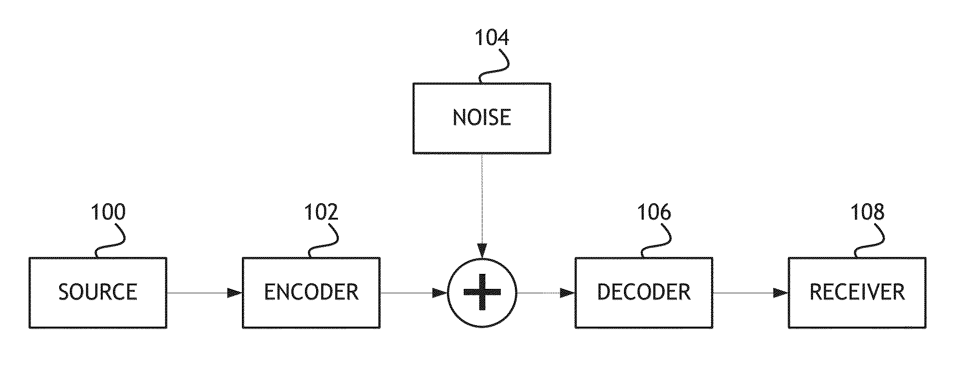
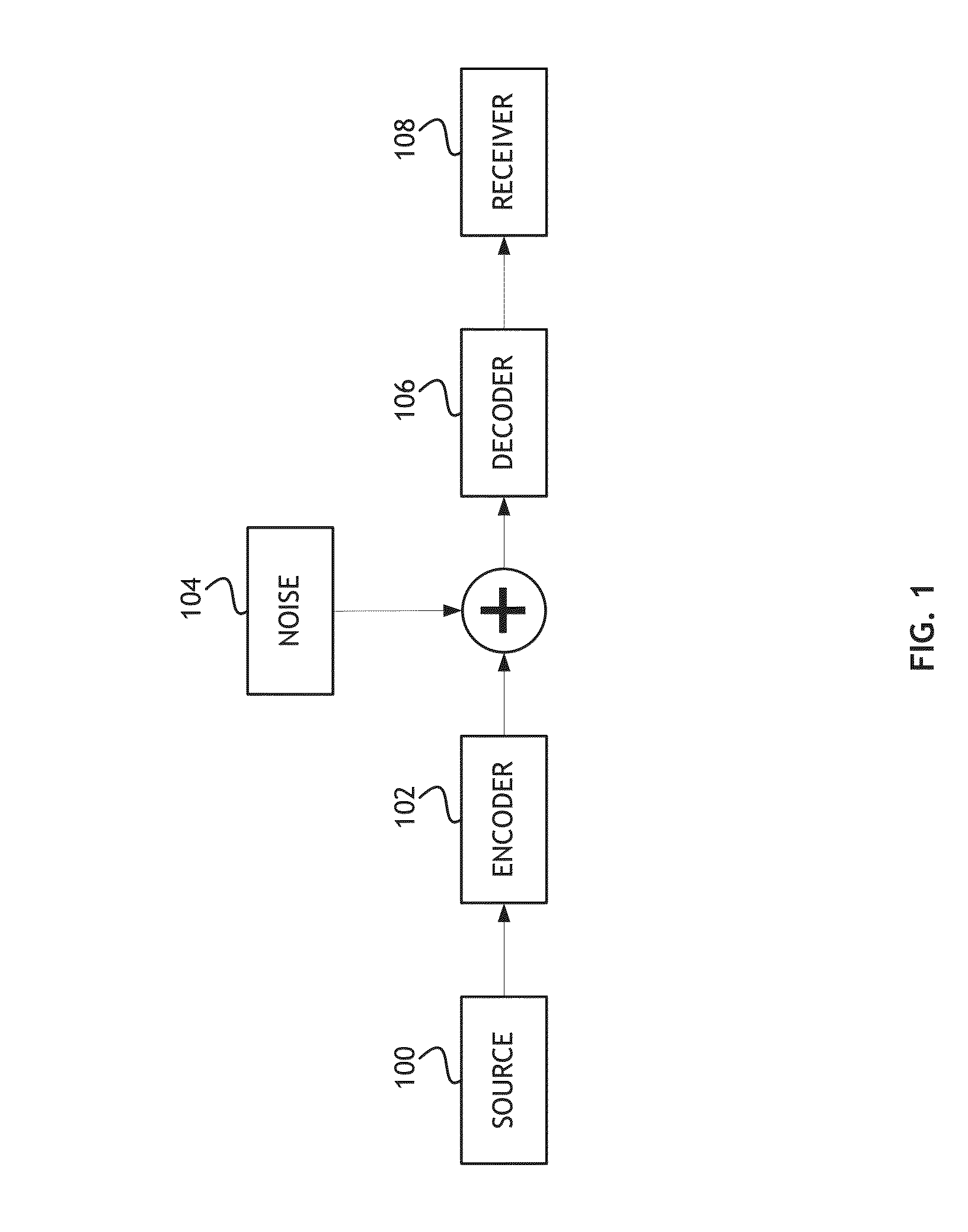
[0028]Referring to FIG. 1, a block diagram of a data transmission path for a low-density parity-check code is shown. In at least one embodiment of the present invention, the standard data transmission path includes a signal source 100 that generates a signal for transmission. The signal produced by the source 100 is encoded by an encoder 102. The encoder 102 is a processor, or computer executable program code embodied in a processor, configured to add features to the signal that enhance data integrity. For example, the encoder 102 adds data b...


PUM


Abstract

A method for estimating error rates in low-density parity check codes includes calibrating an encoder according to specific channel parameters and according to dominant error events in the low-density parity-check code. Dominant codewords are classified based on characteristics of each codeword that are likely to produce similar error rates at similar noise levels; codeword classes that produce the highest error rate are then tested. Error boundary distance is estimated using multiple binary searches on segments. Segments are defined based on codeword, trapping set and biasing noise components of the channel. To improve calculation speed the most significant subclasses of codewords, trapping sets and noise signals are used.

Description

PRIORITY[0001]The present application claims the benefit under 35 U.S.C. §119(a) of Russian Patent Application Serial Number 2013108893, filed Feb. 27, 2013, which is incorporated herein by reference.BACKGROUND OF THE INVENTION[0002]Read channel errors due to noise are rare. Estimating error probability at low noise levels involves selecting dominant error events (dominant trapping sets) and creating a reduced set of input test signals related to those trapping sets to reduce simulation time.[0003]Low-density parity-check codes are linear codes with a sparse parity-check matrix. Sparse here means that the number of non-zero elements is a linear function of the size of the codewords.[0004]It is known that decoding a low-density parity-check code on the binary symmetric channel is an NP-complete problem. So in order to ensure fast (linear) decoding, different techniques based on iterative belief propagation are used and give good approximations. But on the output of such iterative met...

Claims


Application Information

Patent Timeline
Patent Type & Authority Patents(United States)
IPC IPC(8): H03M13/13H03M13/11H03M13/01
CPCH03M13/1102H03M13/015H03M13/1142
Inventor ZAYTSEV, DENIS VLADIMIROVICHMAZURENKO, IVAN LEONIDOVICHPETYUSHKO, ALEXANDER ALEXANDROVICHLETUNOVSKIY, ALEKSEY ALEXANDROVICHALISEITCHIK, PAVEL ALEKSANDROVICHBABIN, DMITRY NICOLAEVICH
Owner AVAGO TECH INT SALES PTE LTD
Why Eureka
Try Eureka