
Fully parallel turbo decoding

a turbo decoder and fully parallel technology, applied in the field of detection circuits, can solve the problems of limiting the end-to-end latency, requiring thousands of time periods to complete the iterative decoding process of the state-of-the-art turbo decoder, and achieving transmission throughput is limited

Active Publication Date: 2019-10-08
ACCELERCOMM LTD
View PDF5 Cites 3 Cited by
  • Summary
  • Abstract
  • Description
  • Claims
  • Application Information

AI Technical Summary

Benefits of technology

The present technique provides a receiver for detecting and recovering data symbols from a received signal using a Markov process. This technique modifies conventional algorithms to improve the processing rate and reduce latency in recovering a data frame. This can be applied to turbo encoders for decoding or other applications such as equalization, synchronization, channel estimation, and source decoding. An improved turbo detection processor can have processing elements that operate autonomously and in parallel, providing a similar processing throughput and latency as fully parallel LDPC decoders. The technique also includes an interleaver that communicates extrinsic information relating to the data symbol and a by-pass circuit that allows selected processing elements to be switched off to save energy consumption. The interleaver can be configured based on a predetermined pattern or accommodate different patterns for different turbo encoders.

Problems solved by technology

However, the achievable transmission throughput is limited by the processing throughput of the iterative decoding algorithm, if real-time operation is required.
Furthermore, the iterative decoding algorithm's processing latency imposes a limit upon the end-to-end latency.
As a result, thousands of time periods are required to complete the iterative decoding process of the state-of-the-art turbo decoder.
Accordingly, providing an alternative to the Log-BCJR decoder, which has fewer data dependencies and which enables fully parallel processing represents a technical problem.

Method used


Image

  • Fully parallel turbo decoding
  • Fully parallel turbo decoding
  • Fully parallel turbo decoding

Examples


Embodiment Construction

Example Communications System

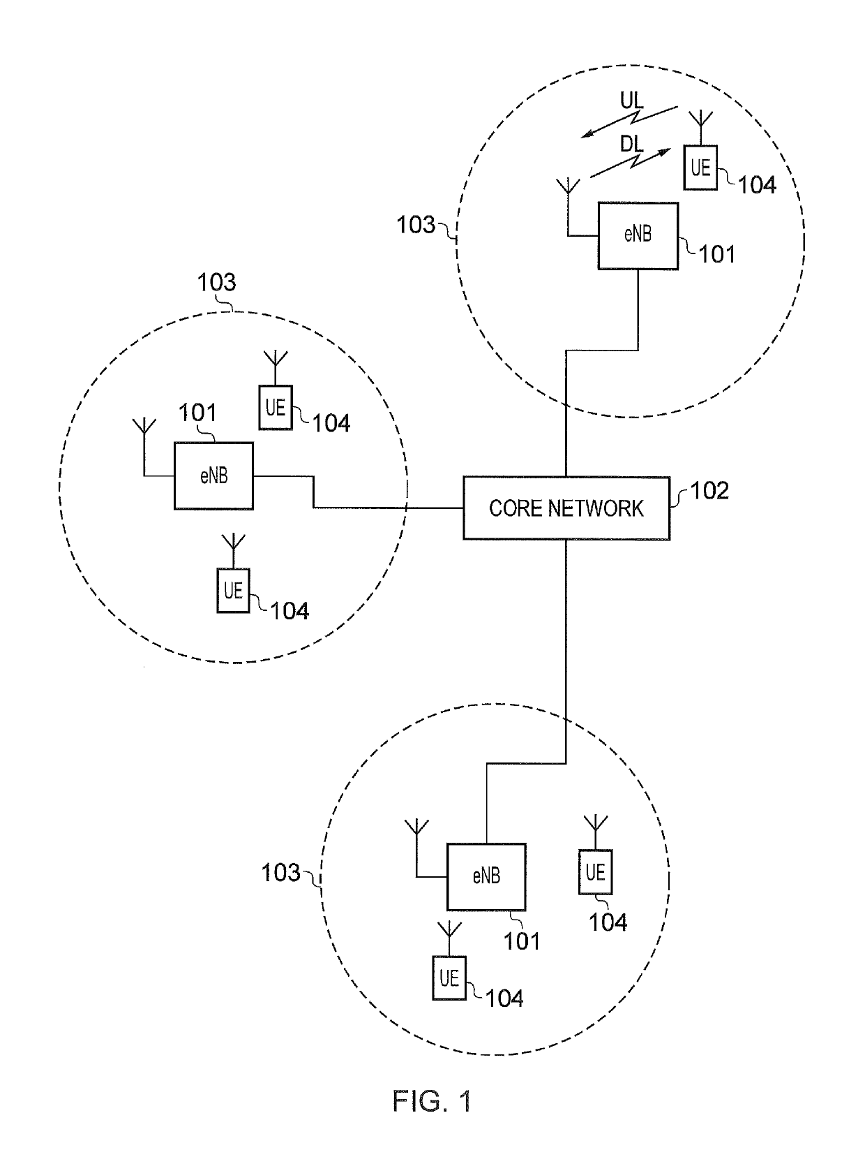
[0039]FIG. 1 provides a schematic diagram of a conventional mobile telecommunications system 100, where the system includes mobile communications devices 101, infrastructure equipment 102 and a core network 103. The infrastructure equipment may also be referred to as a base station, network element, enhanced Node B (eNodeB) or a coordinating entity for example, and provides a wireless access interface to the one or more communications devices within a coverage area or cell. The one or more mobile communications devices may communicate data via the transmission and reception of signals representing data using the wireless access interface. The network entity 102 is communicatively linked to the core network 103 where the core network may be connected to one or more other communications systems or networks which have a similar structure to that formed from communications devices 101 and infrastructure equipment 102. The core network may also provide functi...


PUM


Abstract

A circuit performs a turbo detection process recovering data symbols from a received signal effected, during transmission, by a Markov process with effect that the data symbols are dependent on preceding data symbols represented as a trellis having a plurality of trellis stages. The circuit comprises processing elements, associated with trellis stages representing these dependencies and each configured to receive soft decision values corresponding to associated data symbols Each processing element configured, in one clock cycle to receive data representing a priori forward and backward state metrics, and a priori soft decision values for data symbols detected for the trellis stage. For each clock cycle of the turbo detection process, the circuit processes, for processing elements representing the trellis stages, the a priori information for associated data symbols detected for the trellis stage, and to provide extrinsic soft decision values corresponding to data symbols for a next clock cycle.

Description

TECHNICAL FIELD OF THE DISCLOSURE[0001]The present disclosure relates to detection circuits for performing a turbo detection process to recover a frame of data symbols from a received signal, the data symbols of the frame having been affected, during the process of transmission, by a Markov process with the effect that the data symbols of the frame in the received signal are dependent on one or more preceding data symbols which can be represented as a trellis having a plurality of trellis states. In some examples the detection circuit forms part of a receiver and operates in co-operation with another detection circuit to perform the turbo detection process.[0002]Embodiments of the present disclosure may provide therefore receivers configured to recover the frame of data symbols using a turbo decoder and methods for decoding turbo encoded data. In one example the data symbols are bits.BACKGROUND OF THE DISCLOSURE[0003]Over the past two decades, wireless communication has been revolut...

Claims


Application Information

Patent Timeline
Patent Type & Authority Patents(United States)
IPC IPC(8): H03M13/29H04L1/00H03M13/27H03M13/00H03M13/15H03M13/37H03M13/11H03M13/45
CPCH03M13/6544H03M13/6505H03M13/1575H03M13/45H04L1/0055H03M13/6525H03M13/1111H03M13/3769H04L1/0052H03M13/2771H03M13/3761H03M13/2792H03M13/2957H03M13/6519H03M13/6513H04L1/0071H03M13/617H03M13/6561H04L1/0058H03M13/2789H03M13/27H03M13/2725H04L1/006
Inventor MAUNDER, ROBERTLI, ANPEREZ-ANDRADE, ISAAC
Owner ACCELERCOMM LTD
Learn More