Method and system for computer aided manufacturing measurement analysis

a technology analysis system, applied in the field of computer aided manufacturing measurement (cam2) analysis, can solve the problems of time-consuming, limited in size, scope and effectiveness of the measurement and quality inspection function in the manufacturing process, and something important was missing from the production cycle, so as to facilitate the quality control of manufactured assemblies, and reduce the difficulty of manufacturing

Inactive Publication Date: 2006-02-28
FARO TECH INC
View PDF14 Cites 108 Cited by
  • Summary
  • Abstract
  • Description
  • Claims
  • Application Information

AI Technical Summary

Benefits of technology

[0010]The above discussed and other drawbacks and deficiencies of the prior art are overcome or alleviated by the instant invention. This invention provides a computer-based method and system to facilitate quality control for manufactured assemblies. In particular, the instant method and system assists the measurement of such assemblies and their comparison to large CAD files.
[0011]An embodiment of the invention mitigates the problems encountered with large CAD files by decomposing each of such files into a multi-file format. A large CAD file is thereby broken-down into smaller files that organize the information contained in the larger file. The organization is performed in such a way that the information pertinent to the measurement process is segregated into a different smaller file than the information not needed to calculate measurements. Thus, the computer running the computation accesses a smaller file containing a higher percentage of required information.
[0012]Additionally, assisting the user in coordinating a match-up between the physical surfaces being measured and the proper associated CAD model version of that surface further increases the handling speed. In particular, one embodiment uses selection regions for each surface. A selection region indexes each surface. Thus, when a measurement point is taken, a list of surface regions is automatically scanned in order to determine which region contains that point. The corresponding distance of that measurement point to the surface is then calculated.

Problems solved by technology

Despite these technological advances in design and manufacturing, something important was missing from the production cycle.
Historically, measuring assemblies made of numerous parts against the CAD model has been unwieldy, expensive and unreliable.
Traditionally, the measurement and quality inspection function in the manufacturing process has been time-consuming and limited in size, scope, and effectiveness for a number of reasons.
Manual measurement tools, such as calipers and scales may be slow, imprecise, and always one-dimensional.
Analog test fixtures are costly and inflexible.
Parts must be removed one at a time and transported to the lab for components—which often translates into significant “down time” for the production line.
To date, adaptive measurement hardware and usable CAD-based measurement software have yet to be fully implemented in the manufacturing industry.
Earlier systems required the assembly being measured to be taken to the confines of a quality control lab, which is time consuming and often impractical.
One significant drawback of the current state of technology referred to above is that CAD files demand powerful computers.
Thus, the CAM2 market is limited by the power of the computers generally found and distributed in an affordable way to that market.
It may be common for a company to have one or two powerful and expensive computers in its quality control lab, but unlikely for that same company to have numerous expensive computers distributed throughout a factory.
Since the adaptive measurement hardware devices mentioned above typically are standalone stations assigned at different points in the manufacturing process, cost is a primary concern.
Hence, the requirement to handle the CAD files becomes a limiting factor.
CAD files are usually quite large since they contain information regarding these curves, and points, vectors, various layer settings and other features and information important to each particular CAD format and yet not always relevant to measurement.
Very often, due to the complexity of the numerous surfaces contained in a CAD model, the basic act of selecting a surface can be difficult and time intensive.
Even if the user narrows his or her search to a specific region of the model, those surfaces can sometimes be difficult to distinguish because they overlap, are small, or are grouped closely.

Method used


Image

  • Method and system for computer aided manufacturing measurement analysis
  • Method and system for computer aided manufacturing measurement analysis
  • Method and system for computer aided manufacturing measurement analysis

Examples


Embodiment Construction

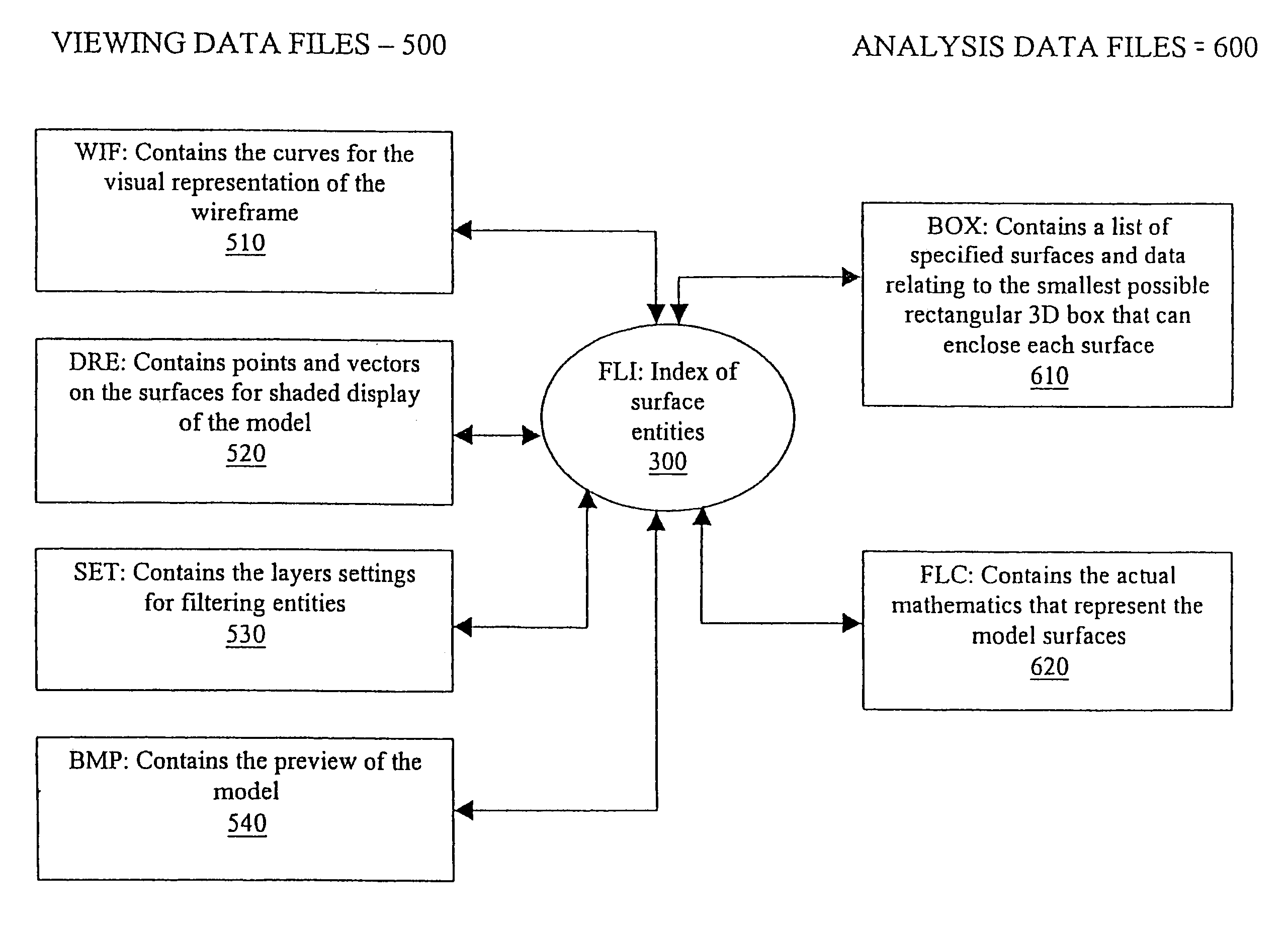
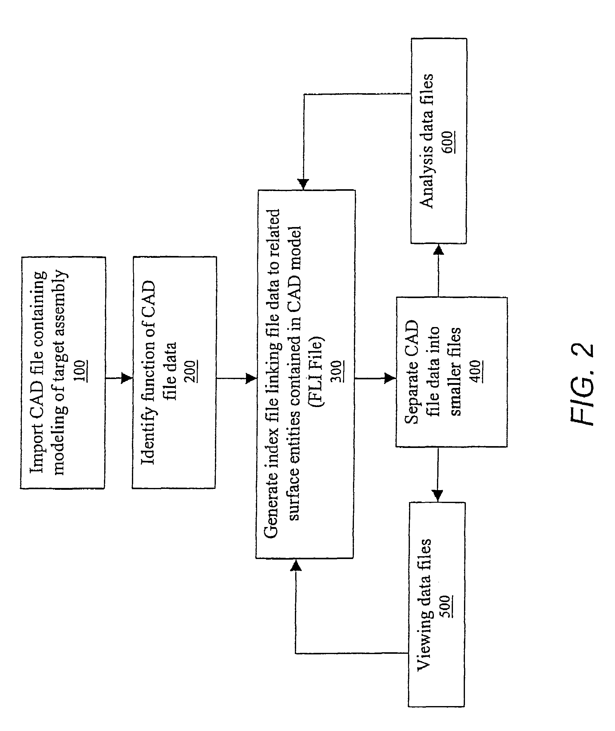
[0019]FIG. 2 is a diagram of the method of managing a large CAD file in one embodiment. The method may be a computer-implemented process in which a microprocessor executes steps in response to a computer program contained in a storage medium. In an exemplary embodiment, the host computer executes the process. Alternatively, a less sophisticated arm-based controller may execute the program as described in U.S. Pat. No. 5,978,748. As shown, a user initiates the process by importing a large CAD file containing a model of an identified assembly at 100. Standard CAD files contain a large number of layers that each includes large stores of information that, while important to the design phase of the model, are not entirely relevant to CAM2. The large CAD file is then analyzed, identifying the function of the data contained therein at 200. Also, each piece of data can be linked to surface entities contained in the CAD model. Thus, in order to not lose track of what data relates to each ent...


PUM


Abstract

The invention relates to a computer-based method and system to facilitate quality control for manufactured assemblies based on computer aided design (CAD) files. The instant invention mitigates the problems encountered with large CAD files by decomposing each of such files into a multi-file format. A large CAD file is thereby broken-down into smaller files that organize the information contained in the larger file. The organization is performed in such a way that the information pertinent to the measurement process is segregated into a different smaller file than the information not needed to calculate measurements. Thus, the computer running the computation accesses a smaller file containing a higher percentage of required information. Additionally, assisting the user in coordinating a match-up between the physical surfaces being measured and the proper associated CAD model version of that surface further increases the handling speed. In particular, the instant invention uses selection regions for each surface. A selection region consists of the representation of a three-dimensional rectangle region just large enough to enclose each individual surface. A selection region indexes each surface. Thus, when a measurement point is taken, a list of surface regions is automatically scanned in order to determine which region contains that point. The corresponding distance of that measurement point to the surface is then calculated.

Description

BACKGROUND[0001]The invention relates to a method and system for computer aided manufacturing measurement (CAM2) analysis. In particular, the instant invention assists in managing large computer-aided design (CAD) files and to the reorganization of the data from those large CAD files into smaller more manageable and quickly accessible files. Further, the instant invention provides for improved CAD model surface selection when comparing manufactured assembly surfaces to the CAD model.[0002]The manufacturing / industrial marketplace commonly uses computer-aided design (CAD) and computer-aided manufacturing (CAM). CAD software allowed engineers to produce 3-D images in the front end of the design process, which shortened the production cycle and led to tremendous gains in productivity. CAM software and equipment increased the efficiency and quality of machined parts. Despite these technological advances in design and manufacturing, something important was missing from the production cycl...

Claims


Application Information

Patent Timeline
Patent Type & Authority Patents(United States)
IPC IPC(8): G06T15/00G01B21/00G05B19/408G05B19/4097G06T17/00
CPCG05B19/408G06T17/00G05B2219/37443G05B2219/35134Y02P90/02
Inventor BUSS, SIEGFRIED KURTQUALITSEN, FRANK FARID
Owner FARO TECH INC
Why Eureka
Try Eureka