Plasma cutting torch, nozzle and shield cap

a shield cap and nozzle technology, applied in plasma welding apparatus, plasma technique, manufacturing tools, etc., can solve problems affecting the operational life of components, and achieve the effects of improving the geometry and configuration improving the geometry of the torch nozzle, and improving the configuration of the inner retaining cap assembly

Active Publication Date: 2016-10-04
LINCOLN GLOBAL INC
View PDF84 Cites 5 Cited by
  • Summary
  • Abstract
  • Description
  • Claims
  • Application Information

AI Technical Summary

Benefits of technology

[0006]Embodiments of the present invention include equipment and methods related to plasma cutting torches and components thereof which are improved over known torches. Embodiments include at least improved torch nozzle geometry and configurations, improved torch geometry, torch profile and shield cap geometry, and improved inner retaining cap assembly configurations. Exemplary torches as described herein have improved durability, precision and operation over known torches, especially in cutting complex 3-D shapes and bevel cuts. Exemplary nozzles include exterior cooling channels and improved configuration, exemplary torches and torch shield caps have improved narrow geometries and profiles, and exemplary inner retainer cap assemblies have improved performance and provide for overall improved torch geometries.

Problems solved by technology

This high heat and spatter adversely affects the operational life of components in the torch, which then require replacement—causing downtime.

Method used


Image

  • Plasma cutting torch, nozzle and shield cap
  • Plasma cutting torch, nozzle and shield cap
  • Plasma cutting torch, nozzle and shield cap

Examples


Embodiment Construction

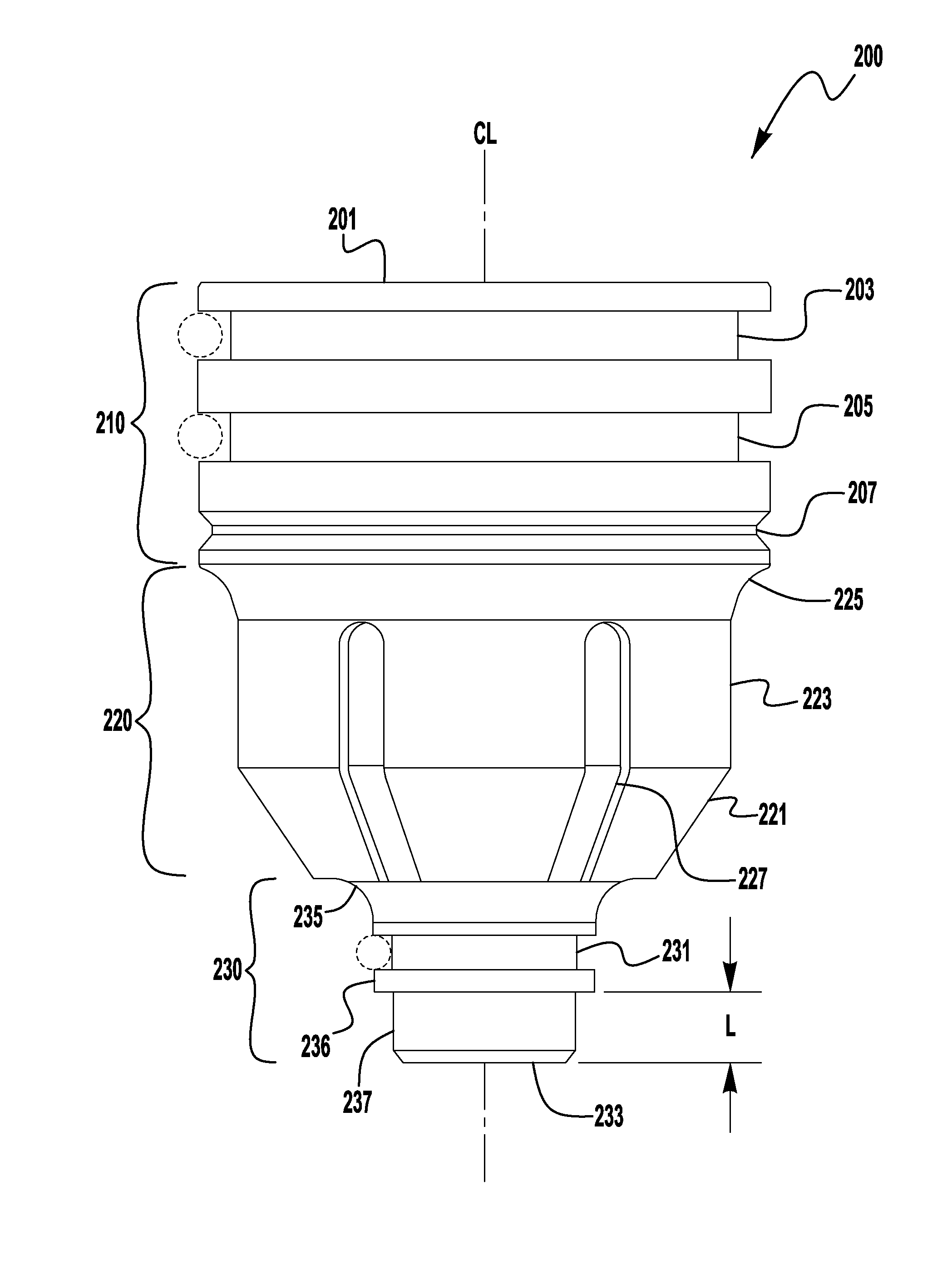
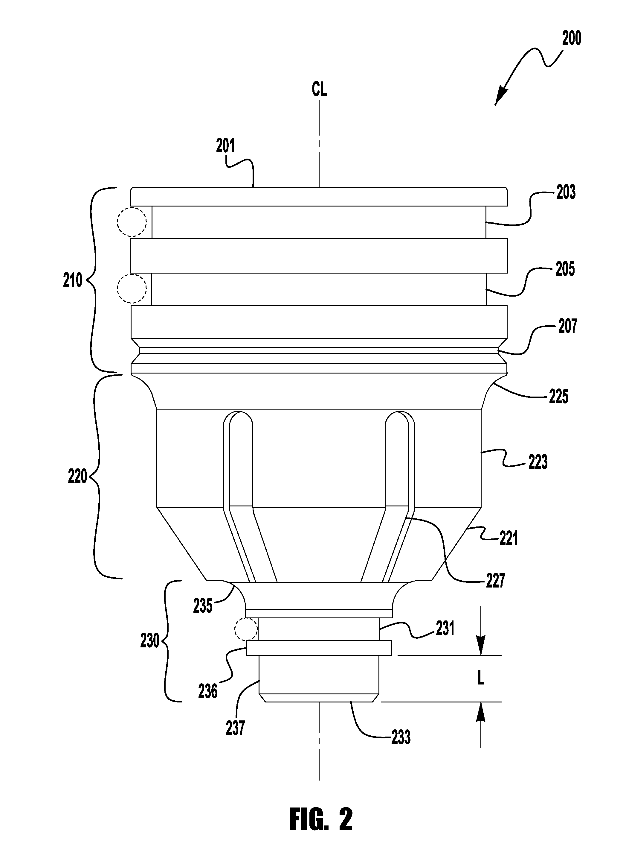
[0016]Exemplary embodiments of the invention will now be described below by reference to the attached Figures. The described exemplary embodiments are intended to assist the understanding of the invention, and are not intended to limit the scope of the invention in any way. Like reference numerals refer to like elements throughout.

[0017]It is noted that for purposes of the following discussion, the system will be discussed as a liquid cooled, mechanized plasma arc cutting system. However, exemplary embodiments are not limited to being used in such arc cutting systems, and embodiments can be used in hand held cutting systems as well as air cooled systems. Thus, the following discussions are intended to be exemplary and informative. Further, discussions below will use terminology such as “distal” and “downstream”. In the context of this application it is understood that these terms mean closer to the end of the torch from which the plasma is emitted. For example, the distal end of the...


PUM

PropertyMeasurementUnit
distanceaaaaaaaaaa
lengthaaaaaaaaaa
distanceaaaaaaaaaa

Abstract

A plasma torch assembly, and components thereof, is provided with optimized attributes to allow for improved torch durability add versatility. A torch nozzle is provided having a novel design, including exterior cooling channels running along a length of the nozzle. An improved inner retaining cap assembly is provided which imparts a swirl on shield gas flow. Additionally, a shield cap and outer retainer have optimized geometries to allow the torch to be made narrower to facilitate the cutting of complex 3-D shapes and bevel cuts not attainable with known mechanized plasma torches.

Description

BACKGROUND OF THE INVENTION[0001]1. Field of the Invention[0002]Systems and methods of the present invention relate to plasma cutting, and more specifically to arc plasma cutting using a torch assembly having a novel nozzle and shielding configuration.[0003]2. Description of the Related Art[0004]The use of plasma cutting systems in various industries has grown, and as a result there is an increasing need to increase the durability and longevity of torches and their components. This is particularly true with regarding to some internal torch parts, such as the nozzle, and some external torch parts, such as the shield cap. As is generally known, plasma cutting involves the use of high current plasma jet which generates a large amount of heat during cutting and can generate spatter during piercing or arc starting. This high heat and spatter adversely affects the operational life of components in the torch, which then require replacement—causing downtime. Accordingly, improvements are ne...

Claims


Application Information

Patent Timeline
Patent Type & Authority Patents(United States)
IPC IPC(8): B23K10/00H05H1/28H05H1/34
CPCB23K10/00H05H1/28H05H1/34H05H2001/3468H05H1/3468
Inventor NAMBURU, PRAVEEN K.
Owner LINCOLN GLOBAL INC
Why Eureka
Try Eureka