Wireless charging receiving device and wireless charging system using the same

a wireless charging and receiving device technology, applied in electric vehicles, electric power, transportation and packaging, etc., can solve the problems of reducing charging efficiency of inductive current, and achieve the effect of improving charging efficiency of wireless charging receiving devices and increasing the inductive current of receiving coils

Active Publication Date: 2016-10-04
HTC CORP
View PDF15 Cites 11 Cited by
  • Summary
  • Abstract
  • Description
  • Claims
  • Application Information

AI Technical Summary

Benefits of technology

[0018]Because the metal housing has at least one slit, the direction of the inductive magnetic field generated by the metal housing is the same as that of the inductive magnetic field generated by the receiving coil. Therefore, it contributes to increase the inductive current of the receiving coil so that the charging efficiency of the wireless charging receiving device is improved.

Problems solved by technology

The magnetic field induced by the inductive current typically reduces charging efficiency.

Method used


Image

  • Wireless charging receiving device and wireless charging system using the same
  • Wireless charging receiving device and wireless charging system using the same
  • Wireless charging receiving device and wireless charging system using the same

Examples


Embodiment Construction

[0026]Reference will now be made in detail to the present embodiments of the invention, examples of which are illustrated in the accompanying drawings. Wherever possible, the same reference numbers are used in the drawings and the description to refer to the same or like parts.

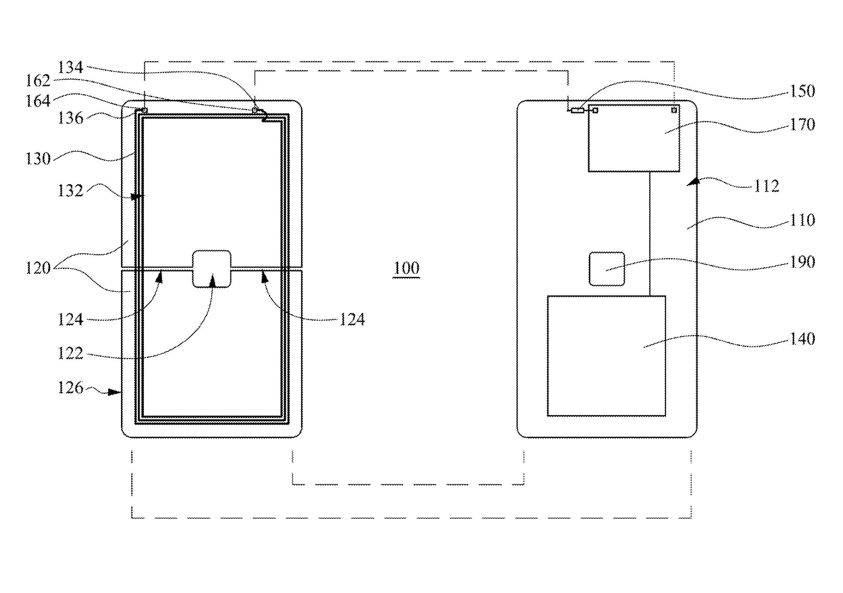
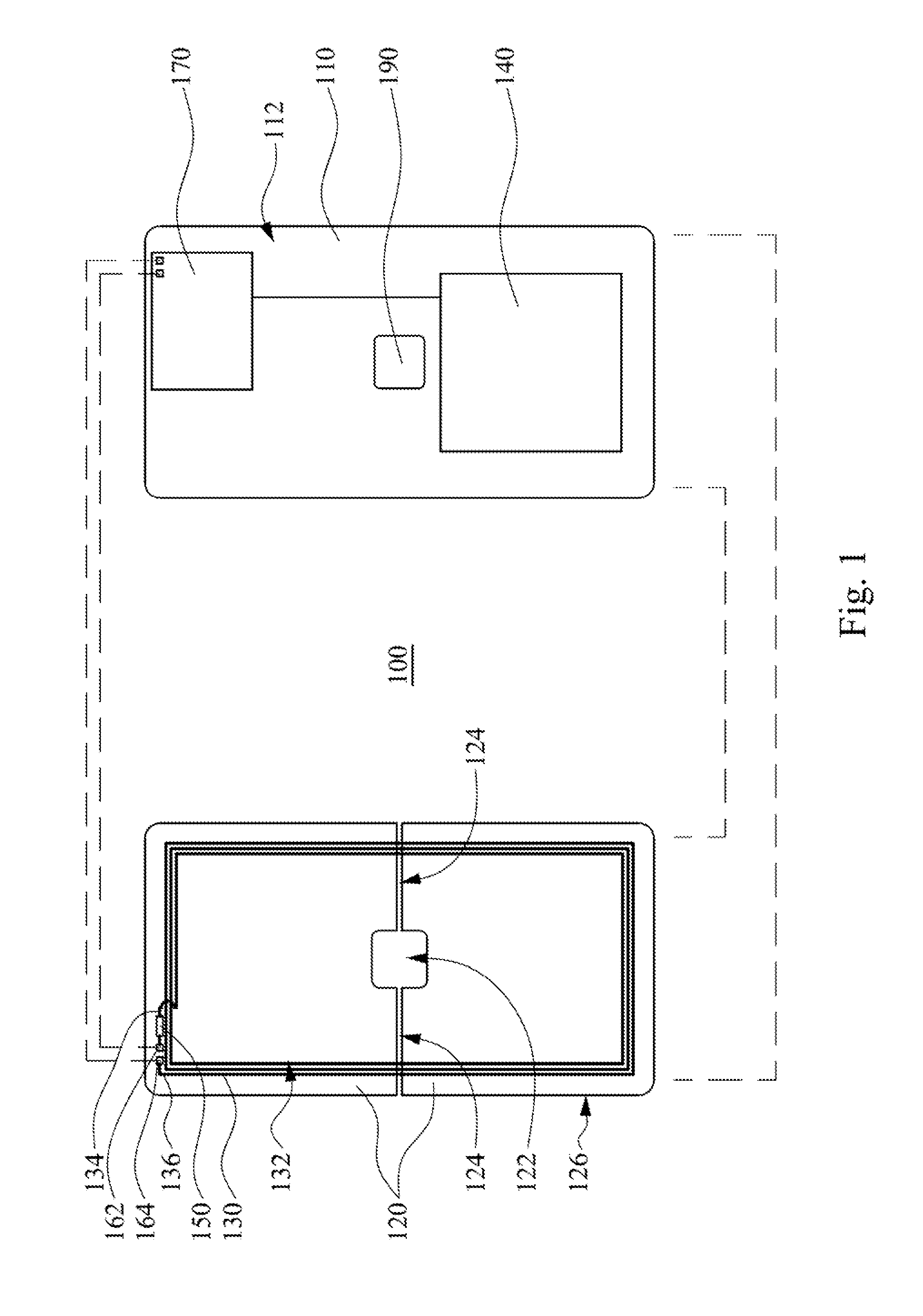
[0027]FIG. 1 is a schematic exploded view of a wireless charging receiving device 100 according to one embodiment of this invention. As shown in FIG. 1, the wireless charging receiving device100 may be, for example, a mobile phone, a laptop computer, a tablet computer, or a handheld device with a communication function. The wireless charging receiving device 100 includes a body 110, a metal housing 120, a receiving coil 130, and a power storage device 140, and may include other elements such as a processor, a substrate, a display element, and a touch input element (not shown). The metal housing 120 is coupled to the body 110 to form an accommodating space. That is, the metal housing 120 covers at least one sur...


PUM


Abstract

A wireless charging receiving device includes a body, a metal housing, a receiving coil, and a power storage device. The metal housing is coupled to the body to form an accommodating space. The metal housing includes an aperture and at least one slit. The slit interconnects the aperture and the edge of the metal housing. The receiving coil is disposed between the metal housing and the body. The receiving coil defines a through hole by a looped configuration, and the through hole overlaps at least part of the aperture of the metal housing. The power storage device is disposed within the accommodating space and electrically connected to the receiving coil. Electromagnetic waves are able to pass through the aperture of the metal housing and are magnetically coupled to the receiving coil, such that the receiving coil transfers the energy of the electromagnetic waves to the power storage device.

Description

BACKGROUND[0001]1. Field of Invention[0002]The subject application relates to a wireless charging receiving device.[0003]2. Description of Related Art[0004]Wireless charging technology utilizes electromagnetic principles to achieve a charging effect. An electronic device may be charged without using a wire so that convenience is improved. Thus, wireless charging technology has become a major area of development in the industry.[0005]However, in order to enhance the aesthetics of an electronic device, a metal housing may be used. For an electronic device with a metal housing, especially a portable electronic device, ten it is wirelessly charged, the metal housing may shield the electromagnetic waves. Even if an aperture is disposed in the metal housing so that electromagnetic waves may pass through the metal housing, inductive current is still generated in the metal housing by the electromagnetic waves. The magnetic field induced by the inductive current typically reduces charging ef...

Claims


Application Information

Patent Timeline
Patent Type & Authority Patents(United States)
IPC IPC(8): H02J7/00H02J7/02
CPCH02J7/025H02J7/0042H02J50/005H02J50/80H02J50/12H02J7/04
Inventor TSENG, CHUN-WEIHO, CHIEN-TINGCHEN, CHIEN-CHIHKUO, YEN-LIANG
Owner HTC CORP
Why Eureka
Try Eureka