Method for operating a gas turbine engine, power supplying device for conducting such method and aircraft using such method

a gas turbine engine and power supply device technology, applied in the direction of turbine/propulsion fuel control, combustion process, fuel cells, etc., can solve the problems of large combustor space, large catalyst space, heavy weight, etc., and achieve the effect of reducing the size or weight of the combustor without increasing the size or weight of the combustor

Active Publication Date: 2016-10-11
AIRBUS SAS
View PDF24 Cites 24 Cited by
  • Summary
  • Abstract
  • Description
  • Claims
  • Application Information

AI Technical Summary

Benefits of technology

[0029]By injection of hydrogen, combustion kinetics is accelerated, so that the combustor size can be small even for low turbine engine power conditions without the risk of un-burnt hydrocarbon and carbon monoxide emissions. Thus, a smaller combustor size can be used without a negative effect for low turbine engine power. The smaller combustor size is advantageous for high turbine engine power conditions to minimize NOX emissions. For high power output operation and a mid-power output operation, hydrogen injection may be stopped to reduce consumption of hydrogen.
[0056]The invention can be applied to gas turbine engines for aeronautics, marine applications and industrial power production. However, the invention is most particularly appropriate for aviation, because aircraft turbine engines are routinely operated at low power for extended periods of times. For example, aircraft engines run at low power while taxiing. Hence, the invention is particularly useful for reducing gaseous emissions of aircraft turbines at airports or the like.

Problems solved by technology

Generally, these combustion systems may emit undesirable compounds such as nitrous oxide compounds (NOX) and carbon-containing compounds.
Such known gas turbine engines have the disadvantage that the catalysts are heavy and take up considerable space within the combustor chamber.
Hence, the whole arrangement is bulky, heavy and complicated.
Such turbine engines exhibit high pressure and high temperature at combustor inlets during high power operations.
This is detrimental to NOX emissions.
In addition, environmental concerns have led, and are likely to lead, to more and more stringent NOX certification requirements.

Method used


Image

  • Method for operating a gas turbine engine, power supplying device for conducting such method and aircraft using such method
  • Method for operating a gas turbine engine, power supplying device for conducting such method and aircraft using such method
  • Method for operating a gas turbine engine, power supplying device for conducting such method and aircraft using such method

Examples


Embodiment Construction

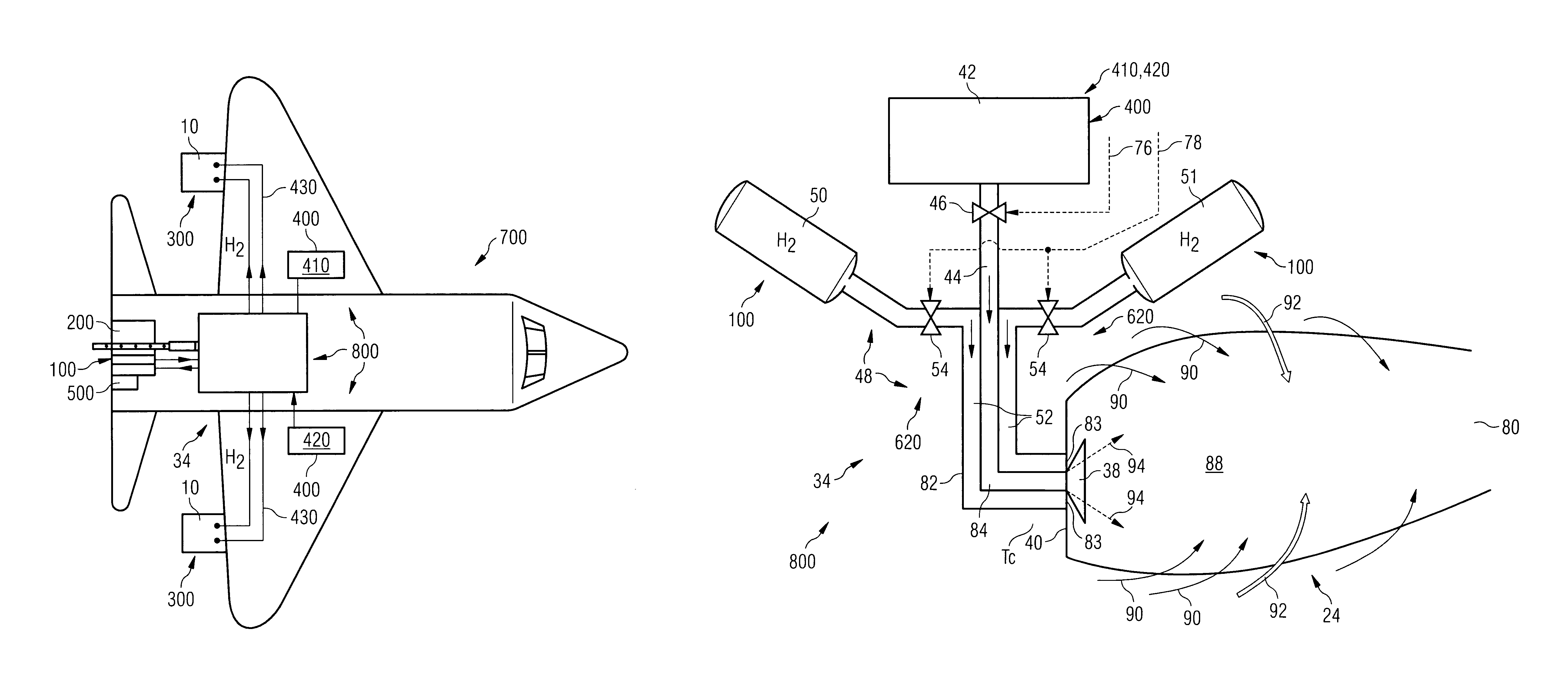
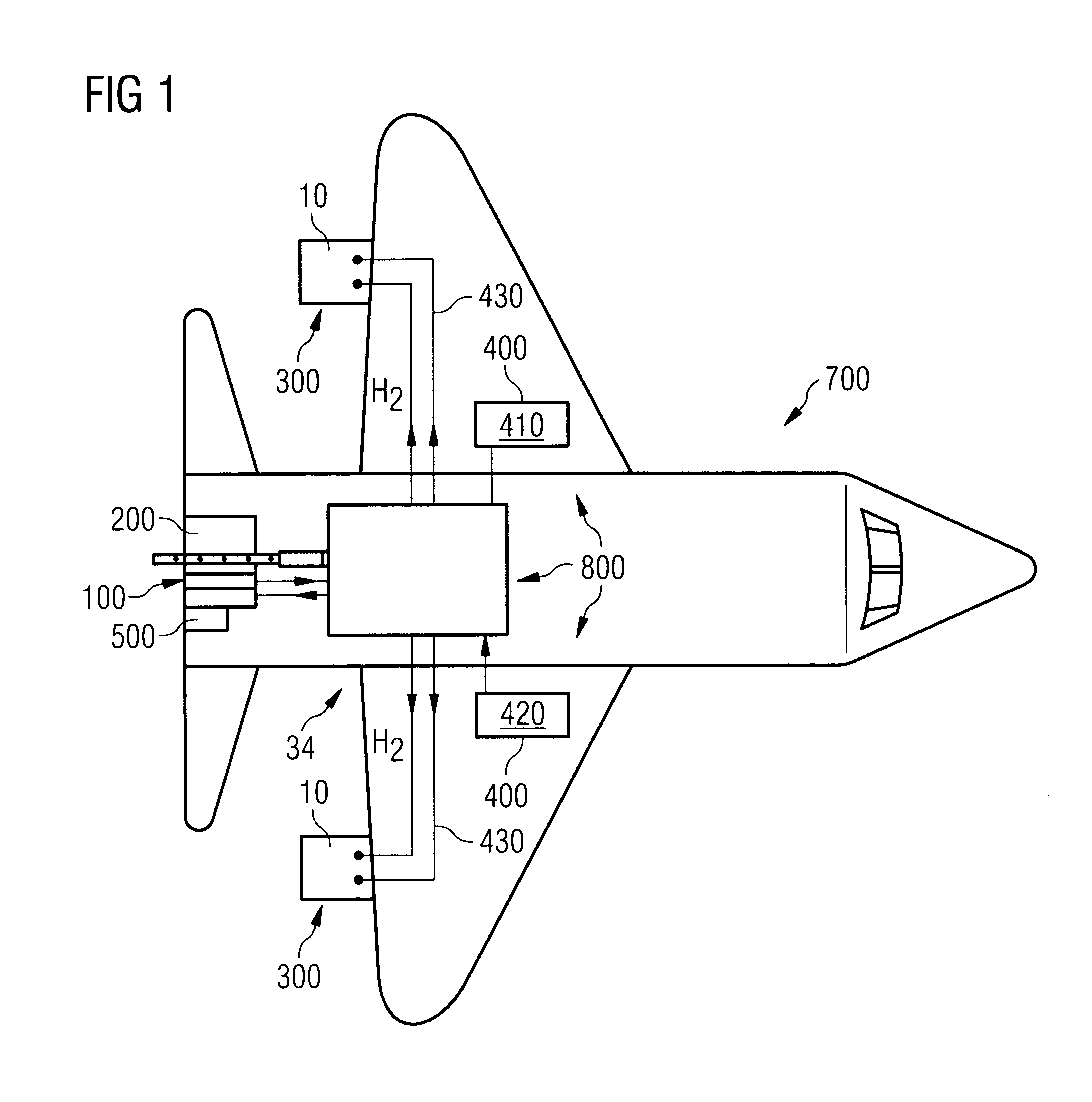
[0065]FIG. 1 shows an aircraft 700, here in form of an airplane, having engines 300 and a power supply device 800.

[0066]The engines 300 are adapted for propulsion of the aircraft 700. The engines 300 and a turbine control system for controlling the engines 300 will be described in greater detail further below.

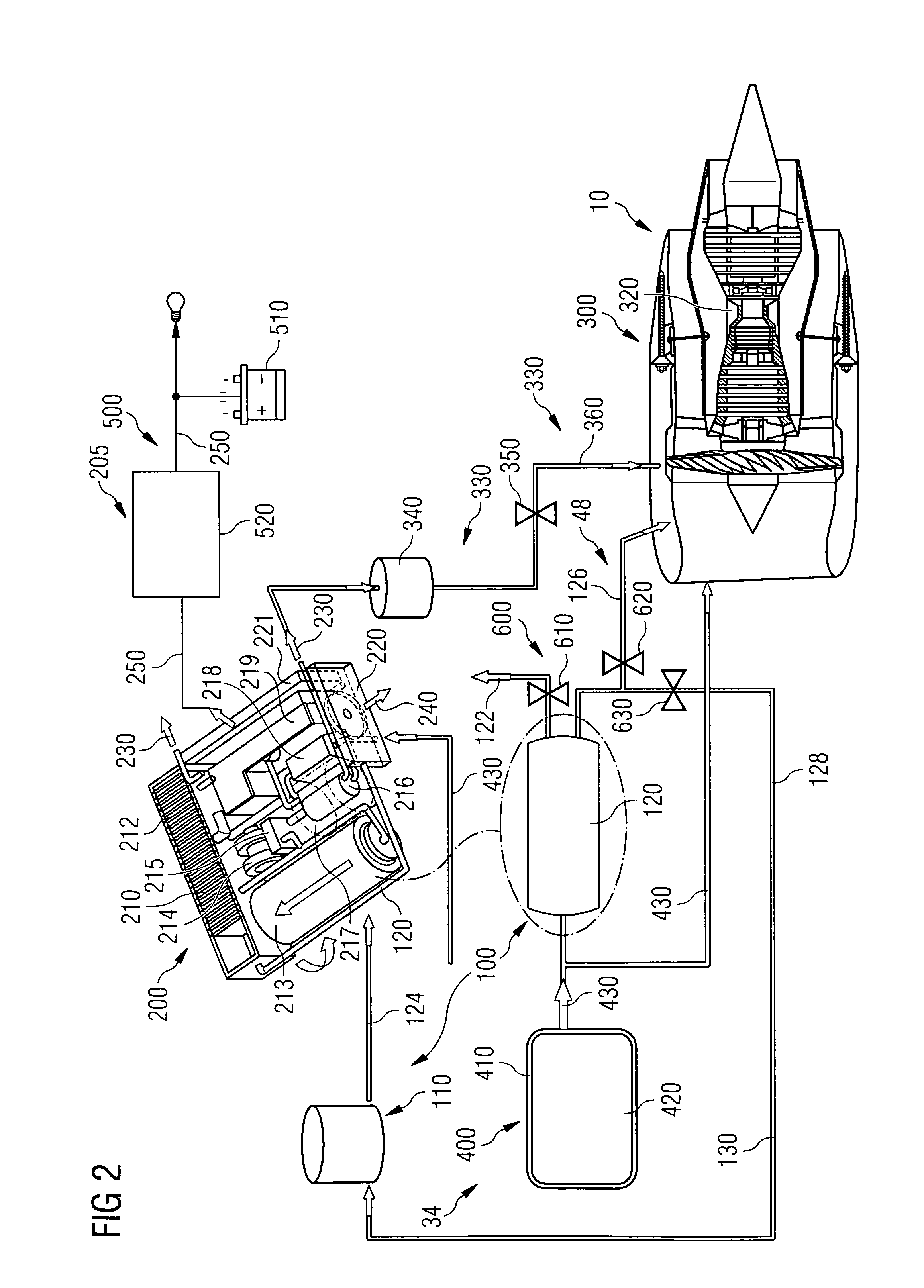
[0067]In the following the power supply device 800 will be explained with reference to FIG. 2. FIG. 2 shows a schematic overview of the power supply device 800 of the aircraft 700 shown in FIG. 1. The power supply device 800 comprises a fuel supply arrangement 34 and an auxiliary power arrangement 205. The fuel supply arrangement 34 includes a hydrogen supply 100 and a hydrocarbon supply 400. The auxiliary power arrangement 205 includes an auxiliary power unit, in the following referred to as APU 200 and an electric system 500.

[0068]In the present example, the hydrocarbon supply 400 has one or several kerosene tanks 410 including a main airplane tank 420 for supply of kerosene ...


PUM


Abstract

A power supply device or system for aeronautics, having a hydrocarbon supply for supplying an engine with hydrocarbon fuel and a hydrogen supply having a fuel reformer for producing hydrogen from hydrocarbon fuel from said hydrocarbon supply. The hydrogen supply is connected to a hydrogen-powered fuel cell for producing electric power and to a hydrogen injecting system for injection of hydrogen into a combustion chamber of the engine. Further, the invention relates to an aircraft having an engine that can be supplied by that power supplying device or system, and to a method for operating said engine.

Description

[0001]This application is a national stage of PCT International Application No PCT / EP2008 / 008095, filed Sep. 24, 2008, which claims priority under 35 U.S.C. §119 to European Patent Application No. 08151335.0, filed Feb. 12, 2008 and claims priority under 35 USC. §120 to U.S. patent application Ser. No. 11 / 861,014, filed Sep. 25, 2007, the entire disclosures of which are herein expressly incorporated by reference.BACKGROUND OF THE INVENTION[0002]The invention relates to a method for operating a gas turbine engine and to a power supplying device for aeronautics, having a hydrocarbon supply for supplying an engine. Further, the present invention relates to an aircraft having a gas turbine engine that can be operated according to such method and / or having such a power supplying device. Especially, the present invention refers to a reduction of gaseous emissions of gas turbine engines, especially in aeronautics.[0003]Typical aeroplanes are using hydrocarbon fuel both for powering the eng...

Claims


Application Information

Patent Timeline
Patent Type & Authority Patents(United States)
IPC IPC(8): F02C7/22F02C3/30F02C3/22F02C9/28F02C9/26F02C9/40F23R3/36F23R3/06
CPCF02C9/40F02C7/22F02C3/22F02C3/30F02C9/26F02C9/28F23R3/06F23R3/36F05D2220/50F05D2270/082F23R2900/00002H01M2250/20Y02T50/675Y02T50/677Y02T50/678Y02T90/32F23C2900/9901H01M8/04156H01M8/0612Y02T50/60Y02T90/40Y02E60/50
Inventor REMY, SEBASTIENBOTTI, JEAN
Owner AIRBUS SAS
Why Eureka
Try Eureka