Driving circuit, driving apparatus, and method for adjusting output impedance to match transmission line impedance by using current adjustment

a driving circuit and output impedance technology, applied in the direction of pulse generator, pulse manipulation, pulse technique, etc., can solve the problems of increasing circuit cost and circuit size of conventional line drivers, and achieve the effects of avoiding attenuated efficiency of signal transmission, minimizing signal reflection, and avoiding impedance mismatch

Active Publication Date: 2016-11-29
FARADAY TECH CORP
View PDF11 Cites 0 Cited by
  • Summary
  • Abstract
  • Description
  • Claims
  • Application Information

AI Technical Summary

Benefits of technology

[0010]In embodiments of the present invention, the scheme used in the driving circuit / apparatus / method can be performed or operated to control / adjust the amount of current passing through corresponding transistors to decide or adjust the output impedance of the above-mentioned driving apparatus / circuit to make the output impedance match with the characteristic impedance of a transmission line before / after the circuit chip leaves the factory, each time when the circuit chip is booted up, or at any timings. This can effectively achieve minimizing signal reflection, avoiding attenuated efficiency for signal transmission, and avoiding impedance mismatch due to semiconductor / resistor process variations.

Problems solved by technology

However, practically, since it is necessary for the conventional line driver to employ the multiple resistors to adjust its output impedance by using voltage adjustment, the circuit size of conventional line driver would inevitably become larger, and the circuit cost would be increased unfortunately.

Method used


Image

  • Driving circuit, driving apparatus, and method for adjusting output impedance to match transmission line impedance by using current adjustment
  • Driving circuit, driving apparatus, and method for adjusting output impedance to match transmission line impedance by using current adjustment
  • Driving circuit, driving apparatus, and method for adjusting output impedance to match transmission line impedance by using current adjustment

Examples


first embodiment

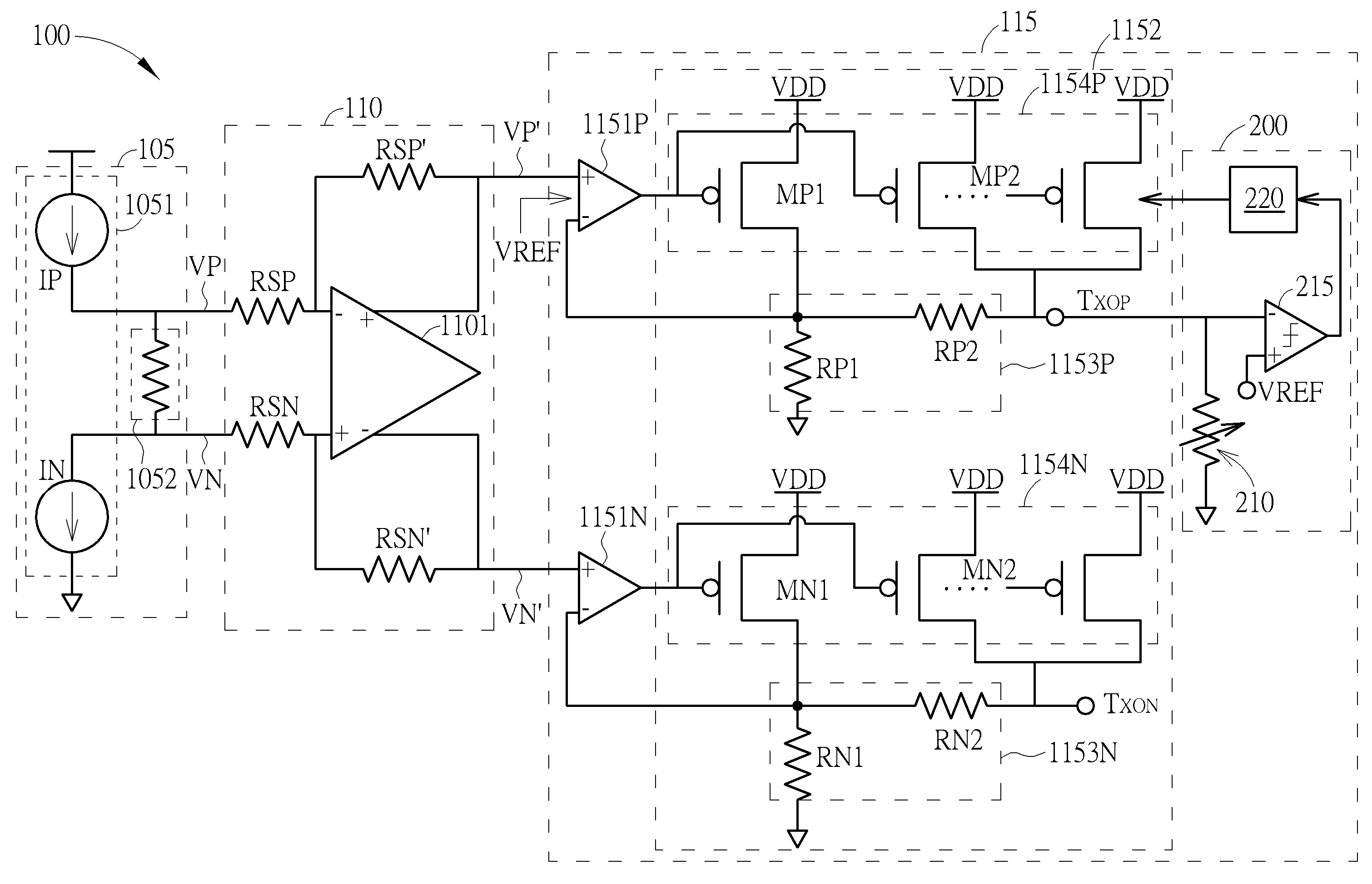
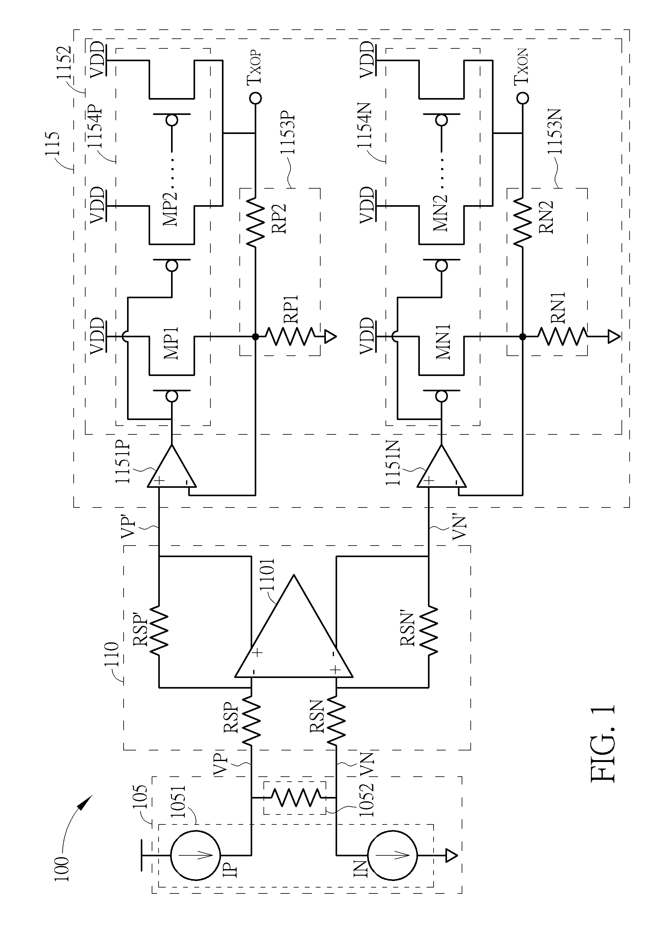
[0016]FIG. 1 is a circuit diagram of a driving apparatus 100 according to the present invention. The driving apparatus 100 is connected to a transmission line such as an Ethernet transmission line. However, this is not meant to be a limitation of the present invention. The driving apparatus 100 is arranged for strengthening or boosting the signal amplitude for a signal inputted to the transmission line. For example, the driving apparatus 100 can strengthening or boosting the signal amplitude for an input signal when receiving the input signal, processing the input signal, and generating an output signal to the transmission line. In addition, in order to avoid or reduce the impedance mismatch caused by semiconductor process variation and / or resistor process variation, the driving apparatus 100 can determine or adjust its output impedance to make the output impedance match the characteristic resistance of the transmission line before / after the circuit chip leaves the factory, each tim...

second embodiment

[0023]Further, the scheme of driving apparatus in the embodiments can be also applied for the transmission line having one single-end output port. Please refer to FIG. 4, which is a circuit diagram of the driving apparatus 400 according to the present invention. The driving apparatus 400 comprises a digital-to-analog converter 405, an amplifying circuit 410, and a driving circuit 415. The digital-to-analog converter 405 comprises a current digital-to-analog converter 4051 and a resistor unit 4052. The current digital-to-analog converter 4051 is used for converting an input signal inputted to the driving apparatus 400 into a current signal. The resistor unit 4052 is used for converting the current signal outputted by the current digital-to-analog converter 4051 into an output voltage signal. The amplifying circuit 410 is coupled to the digital-to-analog converter 405 and utilized for amplifying the output voltage signal to generate an amplified output voltage signal. The amplifying c...


PUM


Abstract

A driving circuit used in a transmission line includes an operational amplifier and an output circuit. The operational amplifier is used for receiving a voltage signal to generate an output. The output circuit is coupled to the operational amplifier and used for receiving the output of the operational amplifier and determining current(s) passing through the output circuit to generate an output signal of the driving signal so as to adjust the output impedance of the driving circuit to match the transmission line; the output impedance of driving circuit is adjustable and determined by the current(s) passing through the output circuit.

Description

BACKGROUND OF THE INVENTION[0001]1. Field of the Invention[0002]The present invention relates to a scheme for adjusting output impedance, and more particularly to a driving apparatus, driving circuit, and corresponding methods for using current adjustment to adjust the output impedance so as to make the output impedance match with the impedance of a transmission line.[0003]2. Description of the Prior Art[0004]Generally speaking, the output impedance of a line driver connected to a transmission line is usually designed to be matched with the characteristic impedance of the transmission line, to minimize signal reflection and avoid attenuated efficiency of signal transmission. A conventional line driver used with a transmission line may adjust resistances of its multiple resistors to adjust the amplitude of its output signal and output impedance to try to make its output impedance be equal to the impedance value specified by the standard of the transmission line, so as to make its out...

Claims


Application Information

Patent Timeline
Patent Type & Authority Patents(United States)
IPC IPC(8): H03K5/12H03H11/28H03K3/012H03F3/45
CPCH03K3/012H03F3/45076H03H11/28H03F2200/255H03F2203/45116H03F2203/45151H03K19/018557H04L25/0278H03F3/45475H03F1/56H03F2200/387H03F2200/423H03F2203/45528
Inventor TSAI, SHAN-JU
Owner FARADAY TECH CORP
Why Eureka
Try Eureka