Female terminal fitting

a terminal fitting and female technology, applied in the direction of coupling contact members, coupling device connections, electrical devices, etc., can solve the problems of impaired reliability of electrical contact, achieve stable regulation of excessive deflection of resilient contact pieces, simplify the configuration of main bodies, and ensure the strength of main bodies

Active Publication Date: 2016-12-06
SUMITOMO WIRING SYST LTD
View PDF111 Cites 5 Cited by
  • Summary
  • Abstract
  • Description
  • Claims
  • Application Information

AI Technical Summary

Benefits of technology

[0008]Since the excessive deflection regulating portion is provided on the base wall of the main body, excessive deflection of the resilient contact piece can be prevented even without forming a hole on a side wall of the main body portion.
[0010]The main body may have an auxiliary spring piece configured to assist a spring force of the resilient contact piece by contacting the resilient contact piece in the deflecting direction of the resilient contact piece. The auxiliary spring piece may be formed by cutting the base wall and bending a cut piece from a hole left on the base wall. The excessive deflection regulating portion also may be cut and bent from the hole. Thus, the excessive deflection regulating portion and the auxiliary spring piece may be provided commonly using one hole so that the configuration of the main body can be simplified. Further, the strength of the main body can be ensured since an unnecessarily large hole is not open on the main body.
[0011]The excessive deflection regulating portion may be be cut and bent from the hole of the base wall and may include a regulating surface at opposite sides of the hole and at positions facing the resilient contact piece. The regulating surface may be raised to be closer to the resilient contact piece than other parts of the base wall. The resilient contact piece comes into line or surface contact with the regulating surface of the excessive deflection regulating portion so that excessive deflection of the resilient contact piece can be regulated stably.
[0012]The female terminal fitting is resiliently lockable by a locking lance projecting at an inner wall of a cavity of a connector housing when being inserted into the cavity, and the main body is provided with a lance receiving space, into which the locking lance is insertable, in a bottom-raising height range of the excessive deflection regulating portion. Since an insertion amount of the locking lance is ensured utilizing the bottom-raised height of the excessive deflection regulating portion, space efficiency is excellent.

Problems solved by technology

Particularly, since the holes are located near a contact portion where the resilient contact piece comes into contact with the male tab, there has been a possibility that an external matter having entered through the hole adheres to the contact portion and there has been a concern that electrical contact reliability is impaired.

Method used


Image

  • Female terminal fitting
  • Female terminal fitting
  • Female terminal fitting

Examples


Embodiment Construction

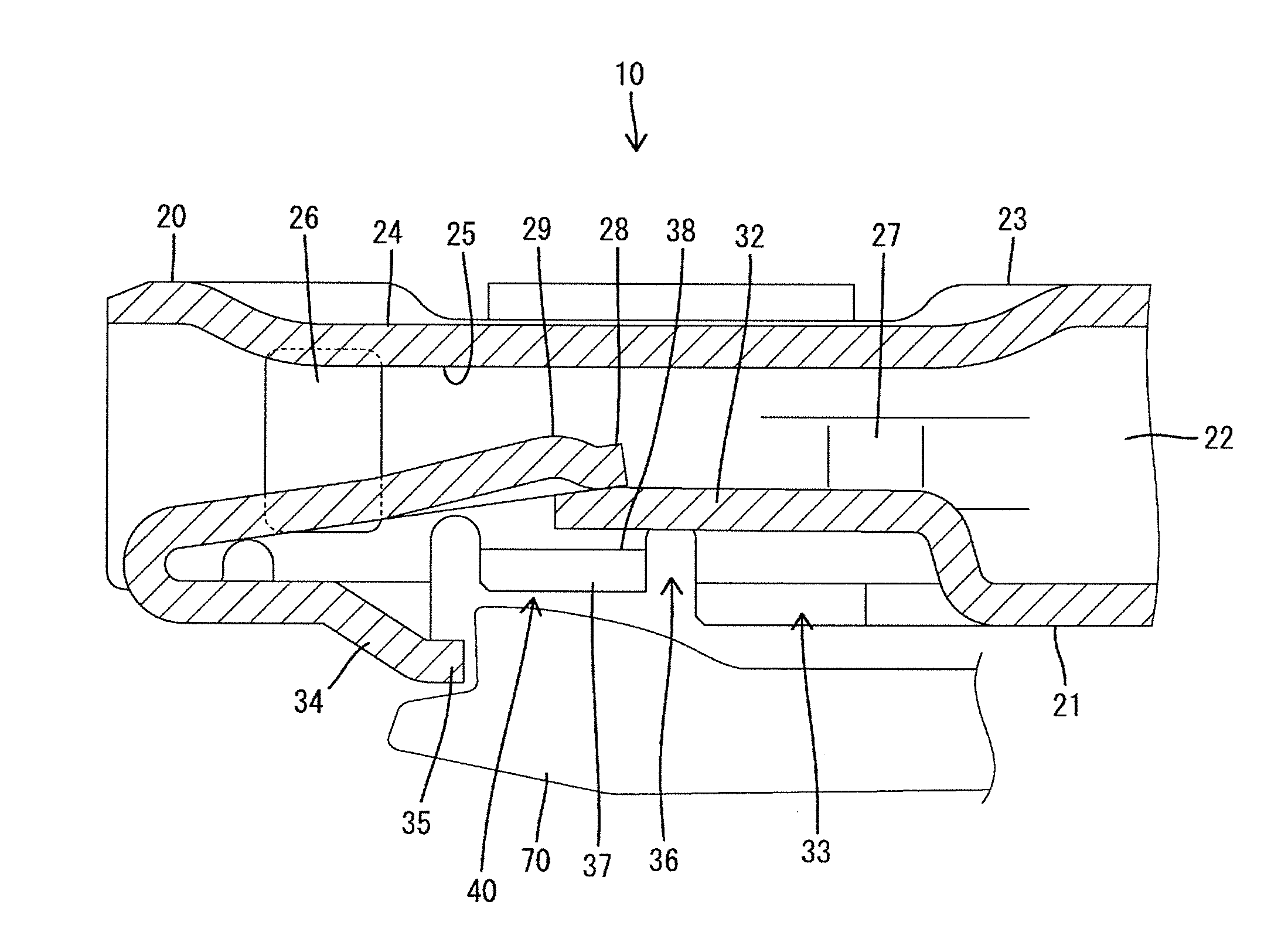
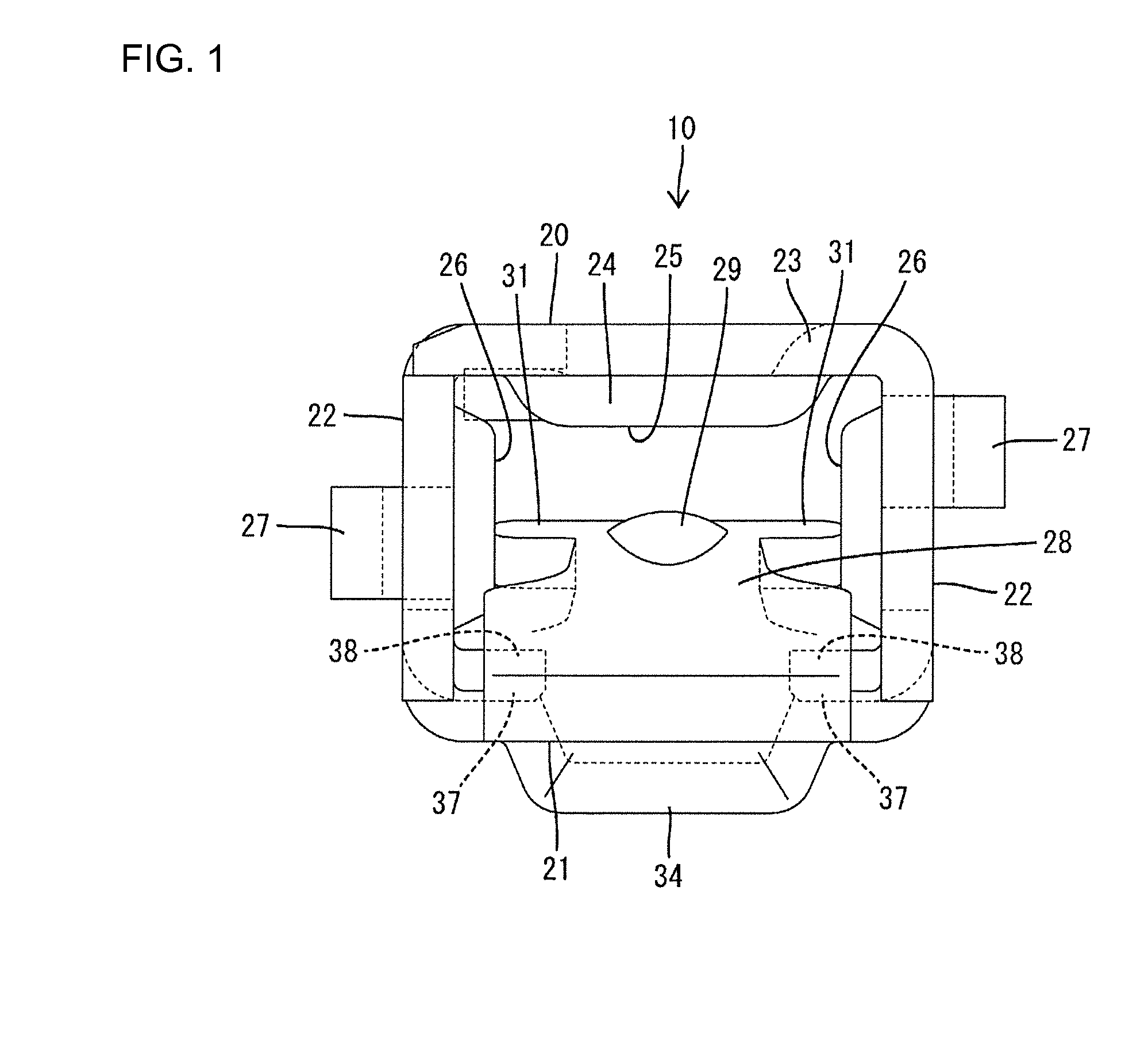
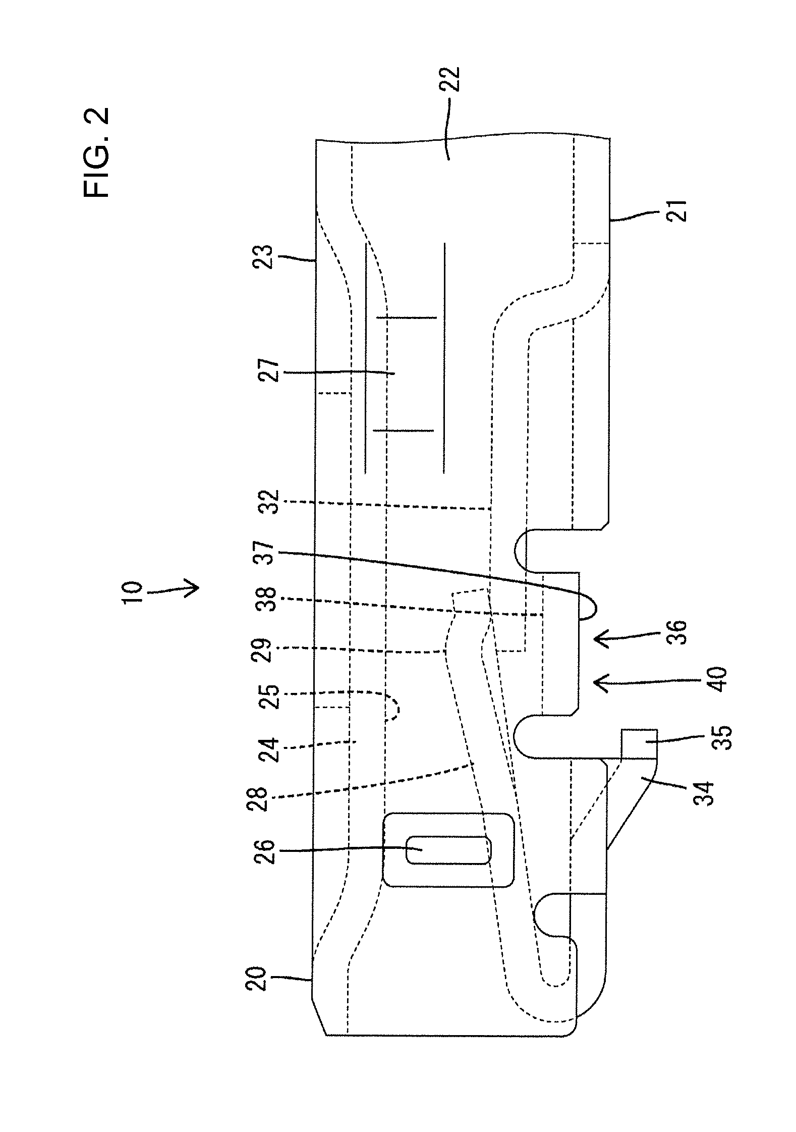
[0020]One embodiment of the present invention is described with reference to FIGS. 1 to 6. A female terminal fitting 10 of the embodiment is formed by applying bending and the like to an electrically conductive metal plate and includes a tubular main body 20 into which a mating male tab 90 (see FIG. 6) is inserted. Note that although the female terminal fitting 10 includes a part to be connected to an end part of a wire (not shown) behind the main body portion 20, this part is neither shown nor described here.

[0021]The main body 20 is in the form of a rectangular tube and, as shown in FIGS. 1 and 5, includes a base wall 21 extending substantially along a width direction, a pair of side walls 22 standing up from opposite widthwise ends of the base wall 21 and a facing wall 23 extending from an upper end part of one side wall 22 to an upper end part of the other side wall 22. A receiving portion 24 bent inwardly of the main body 20 is provided on the facing wall 23. As shown inFIG. 3,...


PUM


Abstract

A female terminal fitting (10) includes a tubular main body (20) and a resilient contact piece (28) deflectably arranged in the main body portion (20). When being inserted into the main body portion (20), a mating male tab (90) comes into contact with the resilient contact piece (28) to deflect and deform the resilient contact piece (28) toward a base wall (21) of the main body portion (20). Excessive deflection regulating portions (37) arranged at positions facing the resilient contact piece (28) in a deflecting direction of the resilient contact piece (28) and configured to regulate excessive deflection of the resilient contact piece (29) are provided on the base wall (21) of the main body portion (20). The excessive deflection regulating portions (37) are bottom-raised toward the resilient contact piece (28) with respect to reference surfaces of the base wall (21).

Description

BACKGROUND[0001]1. Field of the Invention[0002]The present invention relates to a female terminal fitting.[0003]2. Description of the Related Art[0004]A female terminal fitting disclosed in Japanese Unexamined Patent Publication No. 2003-243076 includes a tubular main body portion (called an “electrical contact portion” in Japanese Unexamined Patent Publication No. 2003-243076) into which a male tab is inserted, and a resilient contact piece deflectably arranged in the main body portion and configured to resiliently come into contact with the male tab (called a “male terminal” in Japanese Unexamined Patent Publication No. 2003-243076). Further, excessive deflection preventing pieces formed by being cut and bent inwardly to prevent excessive deflection of the resilient contact piece are provided on opposite side walls of the main body portion.[0005]In the above case, as the excessive deflection preventing pieces are formed, holes are open on the opposite side walls. Thus, there has b...

Claims


Application Information

Patent Timeline
Patent Type & Authority Patents(United States)
IPC IPC(8): H01R4/48H01R13/115H01R13/11
CPCH01R4/48H01R13/113H01R13/115
Inventor CHIKUSA, TAKAHIRO
Owner SUMITOMO WIRING SYST LTD
Why Eureka
Try Eureka