
Ergonomic microbial air sampler

Active Publication Date: 2014-01-16
VALTEK ASSOC INC
View PDF5 Cites 6 Cited by
  • Summary
  • Abstract
  • Description
  • Claims
  • Application Information

AI Technical Summary

Benefits of technology

The invention is a device for sampling viable cells in air. It has a design that reduces the weight of the top plate and improves its contact with the user's fingers, making it easier to lift off. The device also has a concaved sidewall that decreases its weight by approximately 20% and makes it easier for users to lift the top plate off of the bottom plate.

Problems solved by technology

Often, clean rooms are used to work on extremely expensive and complex products, and it is not unusual that there be millions of dollars worth of product in a clean room at any given time.
Clean rooms have to maintain a high level of cleanliness, or risk large financial losses.
If a product being developed or manufactured in a clean room becomes contaminated, the entire product in the clean room must often be discarded.
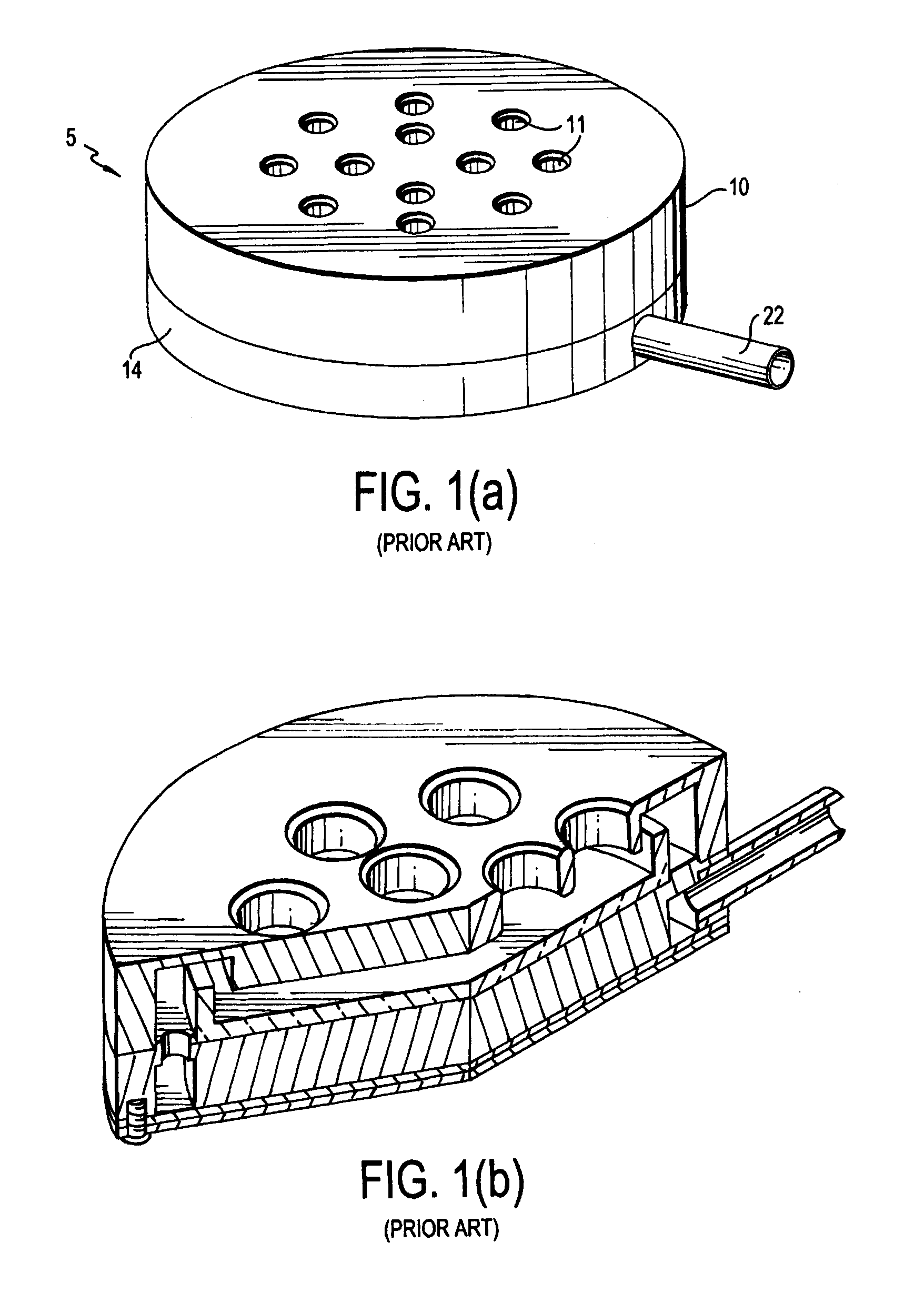
Consequently, the top plate 10 can be difficult to grasp by a person inside the clean room who is wearing gloves.

Method used


Image

  • Ergonomic microbial air sampler
  • Ergonomic microbial air sampler
  • Ergonomic microbial air sampler

Examples


Embodiment Construction

[0020]In describing a preferred embodiment of the invention illustrated in the drawings, specific terminology will be resorted to for the sake of clarity. However, the invention is not intended to be limited to the specific terms so selected, and it is to be understood that each specific term includes all technical equivalents that operate in similar manner to accomplish a similar purpose. Preferred embodiments of the invention are described for illustrative purposes, it being understood that the invention may be embodied in other forms not specifically shown in the drawings.

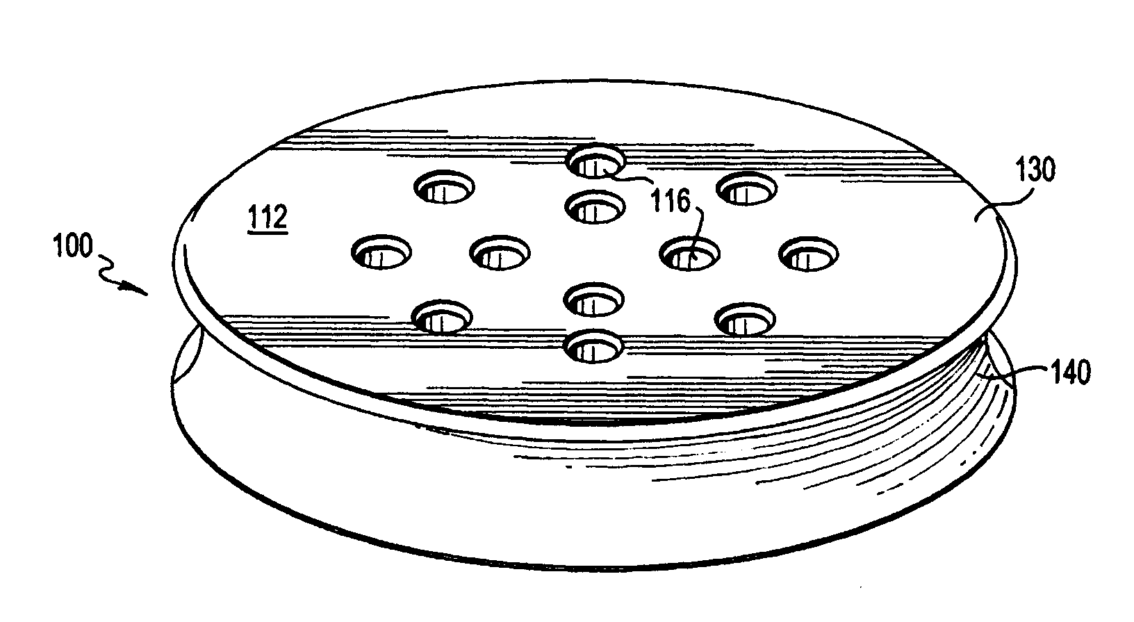
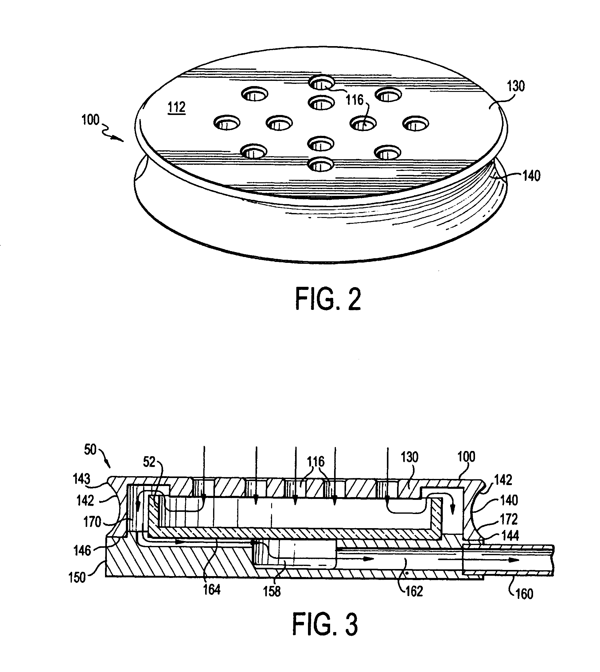
[0021]As shown in FIG. 2, a top plate 100 of an air sampler device 50 is shown. The top plate 100 has a top surface 112. There are twelve holes 116 formed in the top surface 112. The top plate 100 has a flat section 130 and at least one outer side 140. The flat section 130 forms the top surface of the top plate 100 and extends substantially horizontally when in use. The openings 116 pass through the flat section...


PUM


Abstract

A gas sampler device has a top plate with a concaved outer wall. The concaved outer wall allows users easily to lift the top plate off of the bottom plate without disturbing the bottom plate because the curved surface permits more positive contact between the outer wall and users' fingers. Moreover, the weight of the top plate is reduced by approximately twenty percent compared to conventional top plates, a feature that also makes it easier for users to lift the top plate off of the bottom plate.

Description

BACKGROUND OF THE INVENTION[0001]1. Field of the Invention[0002]The present invention relates to a microbiological gas sampler. More particularly, the present invention is for a microbiological gas sampler for use in a controlled environment that includes an ergonomic top plate with concaved sidewalls. The concaved sidewalls allow both more positive contact when attempting to grasp the top plate and a reduction of the weight of the device.[0003]2. Background of the Related Art[0004]A controlled environment is an area which is designed, maintained, or controlled to prevent particle and microbiological contamination of products. Controlled environments include, for example, clean rooms and clean hoods. There are different levels of cleanliness in clean rooms, generally in the range of a Class 100 room (i.e., a room having no more than 100 particles of 0.5 micron and larger, per cubic foot of air), to a Class 10,000 clean room.[0005]Clean rooms are used for a variety of purposes, such ...

Claims


Application Information

Patent Timeline
IPC IPC(8): G01N1/26
CPCG01N1/2273G01N2001/2276G01N2001/2291B65D43/06G01N1/22B65D23/102B65D7/04
Inventor VELLUTATO, JR., ARTHUR L.
Owner VALTEK ASSOC INC
Learn More