Fluid ejecting apparatus and wiping method

a technology of ejecting apparatus and wiping method, which is applied in the direction of printing, etc., can solve the problems of insufficient supply of ink to the nozzle, waste of ink by continuously flowing down the wiper, etc., and achieve the suppression of suppressing the consumption of the fluid involved, and suppressing the occurrence of dot omission

Active Publication Date: 2013-06-18
SEIKO EPSON CORP
View PDF8 Cites 6 Cited by
  • Summary
  • Abstract
  • Description
  • Claims
  • Application Information

AI Technical Summary

Benefits of technology

[0010]An advantage of some aspects of the invention is that it provides a fluid ejecting apparatus and a wiping method, which allow the occurrence of dot omission to be suppressed while suppressing consumption of fluid involved in wiping.
[0012]According to this configuration, since at the time of wiping, the pressurization mechanism applies pressure to the fluid in the fluid ejecting head, in a case where the wiper has drawn out the fluid from the inside of the nozzle, the fluid is promptly supplied into the nozzle. By doing so, occurrence of dot omission can be suppressed. Also, changes in pressure by the pressurization mechanism are applied in a minute range of an extent that changes the curvature of the liquid surface in the nozzle without moving the position of the boundary of the liquid surface. For this reason, since contact between the wiper and the liquid surface is only for a short time while the wiper enters into and passes through the nozzle, continuous outflow of fluid is not caused. Therefore, it is possible to suppress the occurrence of dot omission while suppressing the consumption of fluid involved in wiping.
[0014]According to this configuration, since the pressurization mechanism applies pressure in such a manner that the position of the boundary of the liquid surface is fixed while the pressure is applied, and also in which the central area the liquid surface does not spill out from the nozzle orifices, excessive contact between the liquid surface and the wiper due to the protruding of the liquid surface from the nozzle orifices can be suppressed.
[0016]According to this configuration, since the water repellent treatment is carried out in the vicinity of the nozzle orifice, the liquid surface retreats further inward than the water repellent treatment portion in which the water repellent is carried out. Therefore, even if the pressure of the fluid in the fluid ejecting head, which becomes the back pressure of the liquid, is set to be equal to or greater than the pressure of the gas that comes into contact with the liquid surface, so that a convex liquid surface is formed in the nozzle, excessive contact of the liquid surface with the wiper due to the protruding of the liquid surface from the nozzle orifices can be suppressed. Also, the occurrence of dot omission can be further suppressed by making the back pressure of the liquid positive pressure in this manner.
[0020]According to this configuration, since the pressurization mechanism applies pressure so that the curvature of the liquid surface becomes smaller than that at the time of decompression, it is possible to bring the pressure of the fluid in the fluid ejecting head at the time of wiping close to the pressure of the gas that comes into contact with the liquid surface. As a result, it is possible to suppress the occurrence of dot omission while suppressing the consumption of fluid involved in wiping.
[0022]According to this configuration, since the fluid in the fluid ejecting head is pressurized during the wiping, in a case where the wiper has drawn out fluid from the inside of the nozzle, the fluid is promptly supplied into the nozzle. By doing so, dot omission can be suppressed. Also, changes in the pressure by pressurization are applied in a minute range of an extent that changes the curvature of the liquid surface in the nozzle without moving the position of the boundary of the liquid surface that comes into contact with the nozzle. For this reason, since the contact between the wiper and the liquid surface is only for a short time while the wiper enters into and passes through the nozzle, continuous outflow of the fluid is avoided. Therefore, it is possible to suppress the occurrence of dot omission while suppressing the consumption of the fluid involved in wiping.

Problems solved by technology

However, since the pressure at the back side of a liquid in the nozzle is normally set to be negative pressure, the ink is not sufficiently supplied to the nozzle when wiping is performed at high speed.
However, if the wiper comes into contact with the liquid surface exuded to the nozzle formation face, since the back pressure is positive pressure, there is a problem in which ink is wasted by continuously flowing out down the wiper.

Method used


Image

  • Fluid ejecting apparatus and wiping method
  • Fluid ejecting apparatus and wiping method
  • Fluid ejecting apparatus and wiping method

Examples


first embodiment

[0031]Hereinafter, the first embodiment that embodies the invention in an ink jet printer (hereinafter simply referred to as a “printer”) which is one type of a fluid ejecting apparatus will be described with reference to FIGS. 1 to 6. In addition, a “front-and-back direction”, a “right-and-left direction”, and an “up-and-down direction”, as mentioned in the following explanation, are respectively set to represent a front-and-back direction, a right-and-left direction, and an up-and-down direction, that are indicated by arrows in each drawing.

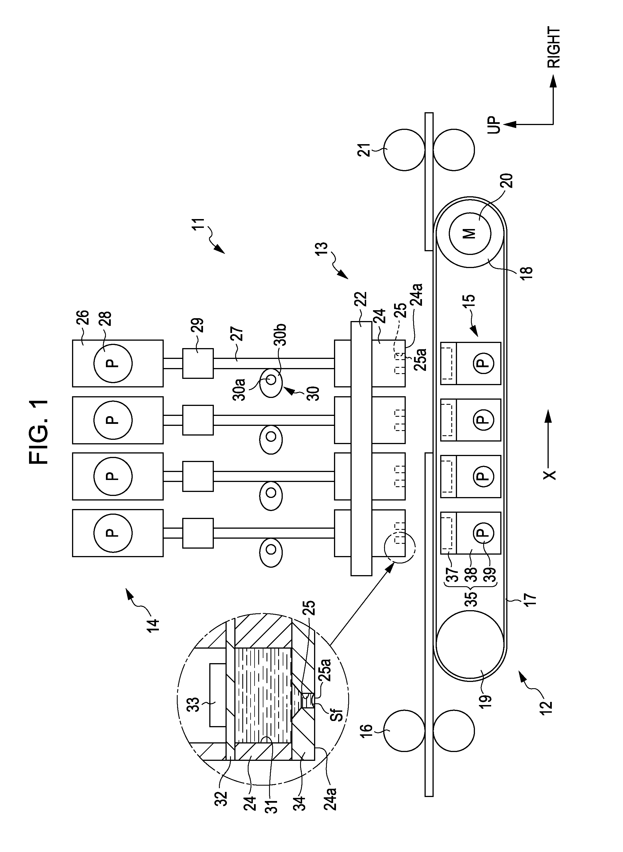
[0032]As shown in FIG. 1, a printer 11 includes a transport mechanism 12 which transports paper P as a medium, a line head 13 that performs printing process on the paper P, an ink supply unit 14 which supplies ink as fluid to the line head 13, and a maintenance unit 15.

[0033]The transport mechanism 12 includes a pair of paper feed rollers 16, an endless transport belt 17, a driving roller 18, a driven roller 19, a driving motor 20 connected to ...

second embodiment

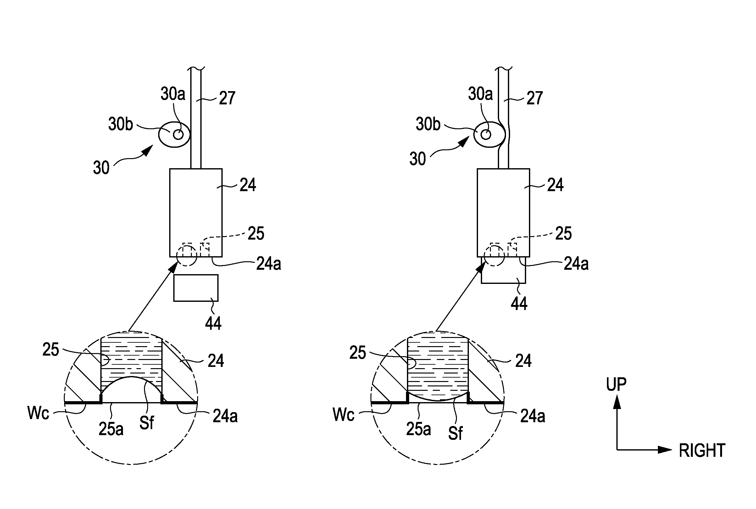
[0080]Next, the second embodiment of the invention will be described based on FIGS. 7A and 7B.

[0081]In the printer 11 of this embodiment, as shown in FIGS. 7A and 7B, a water repellent treatment is carried out at the nozzle formation face 24a of the fluid ejecting head 24 and in the vicinity of the nozzle orifice 25a of the nozzle 25. In addition, the portion marked by a thick line in FIGS. 7A and 7B, in which the water repellent treatment is carried out, is referred to as a water repellent treatment portion Wc. For this reason, the liquid surface Sf in the nozzle 25 retreats further inward than the water repellent treatment portion Wc, as shown in FIG. 7A, whereby the boundary of the liquid surface Sf is formed at an end portion (an upper end portion) of the water repellent treatment portion Wc.

[0082]For this reason, in this embodiment, even when the back pressure is set to be equal to or greater than the atmospheric pressure, so that a convex liquid surface Sf is formed, as shown ...


PUM


Abstract

A fluid ejecting apparatus includes: a fluid ejecting head in which nozzles that eject fluid are provided; a wiper that wipes a nozzle formation face, in which nozzle orifices of the nozzles are formed, in the fluid ejecting head; and a pressurization mechanism which changes the curvature of a concave liquid surface formed in the nozzle, in the nozzle by performing pressurization on the fluid in the fluid ejecting head at the time of the wiping.

Description

BACKGROUND[0001]1. Technical Field[0002]The present invention relates to a fluid ejecting apparatus and a wiping method of the fluid ejecting apparatus.[0003]2. Related Art[0004]Heretofore, ink jet printers have been widely known as fluid ejecting apparatuses that eject fluid onto a medium. Such a printer is made so as to perform a printing process on paper (the medium) by ejecting ink (the fluid) from nozzles formed in a fluid ejecting head.[0005]In such a printer, in order to stably eject ink droplets from the nozzles of the fluid ejecting head, the pressure in the fluid ejecting head, which is applied as a back pressure of a liquid in the nozzle, was normally set negative lower than the atmospheric pressure. In addition, such printers were sometimes provided with wipers for slidingly removing adherent materials (thickened ink, paper dust, and the like) formed on the nozzle formation face, on which the nozzle orifices are formed, of the fluid ejecting head (for example, JP-A-2001-...

Claims


Application Information

Patent Timeline
Patent Type & Authority Patents(United States)
IPC IPC(8): B41J2/165
CPCB41J2/16526B41J2/16585B41J2/16535
Inventor YAMADA, YOICHIKOBASHI, MASARUKATSUKI, KIYOTERU
Owner SEIKO EPSON CORP
Why Eureka
Try Eureka