Variable displacement pump, oil jet and lublicating system using variable displacement pump

A fuel injector and capacity technology, applied to parts, pumps, pump components, etc. of pumping devices used for elastic fluids, can solve problems such as energy consumption, and achieve the effect of suppressing energy consumption

Inactive Publication Date: 2011-08-10
HITACHI AUTOMOTIVE SYST LTD
View PDF6 Cites 16 Cited by
  • Summary
  • Abstract
  • Description
  • Claims
  • Application Information

AI Technical Summary

Problems solved by technology

[0006] However, when the above-mentioned conventional variable displacement pump is applied to an apparatus for supplying oil to an oil injector for cooling the piston of an internal combustion engine, if the above-mentioned first discharge pressure of the variable displacement pump is In this stage, oil is supplied to the injector before the cam ring moves, and unnecessary energy may be consumed until the discharge pressure for moving the cam ring is obtained.

Method used


Image

  • Variable displacement pump, oil jet and lublicating system using variable displacement pump
  • Variable displacement pump, oil jet and lublicating system using variable displacement pump
  • Variable displacement pump, oil jet and lublicating system using variable displacement pump

Examples


no. 1 approach

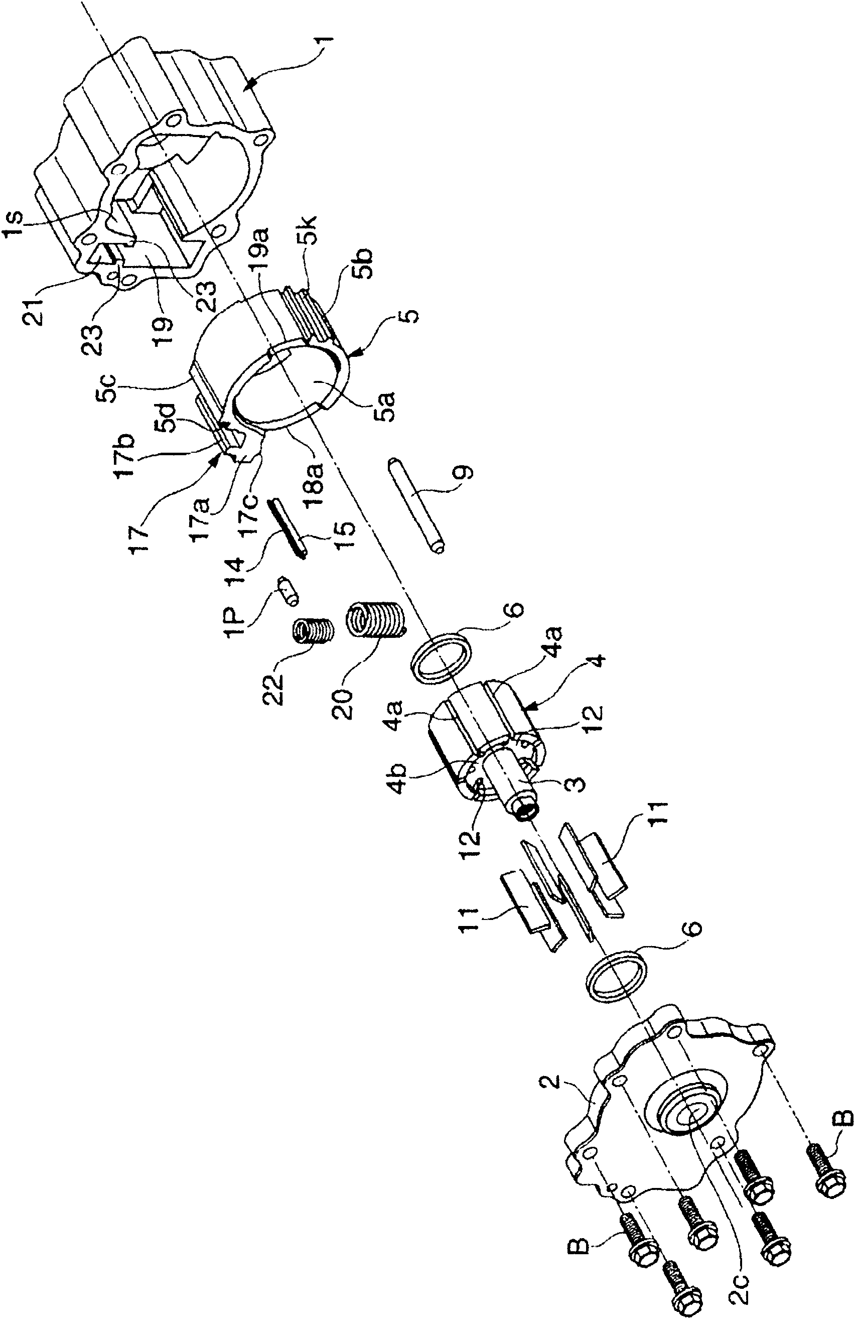
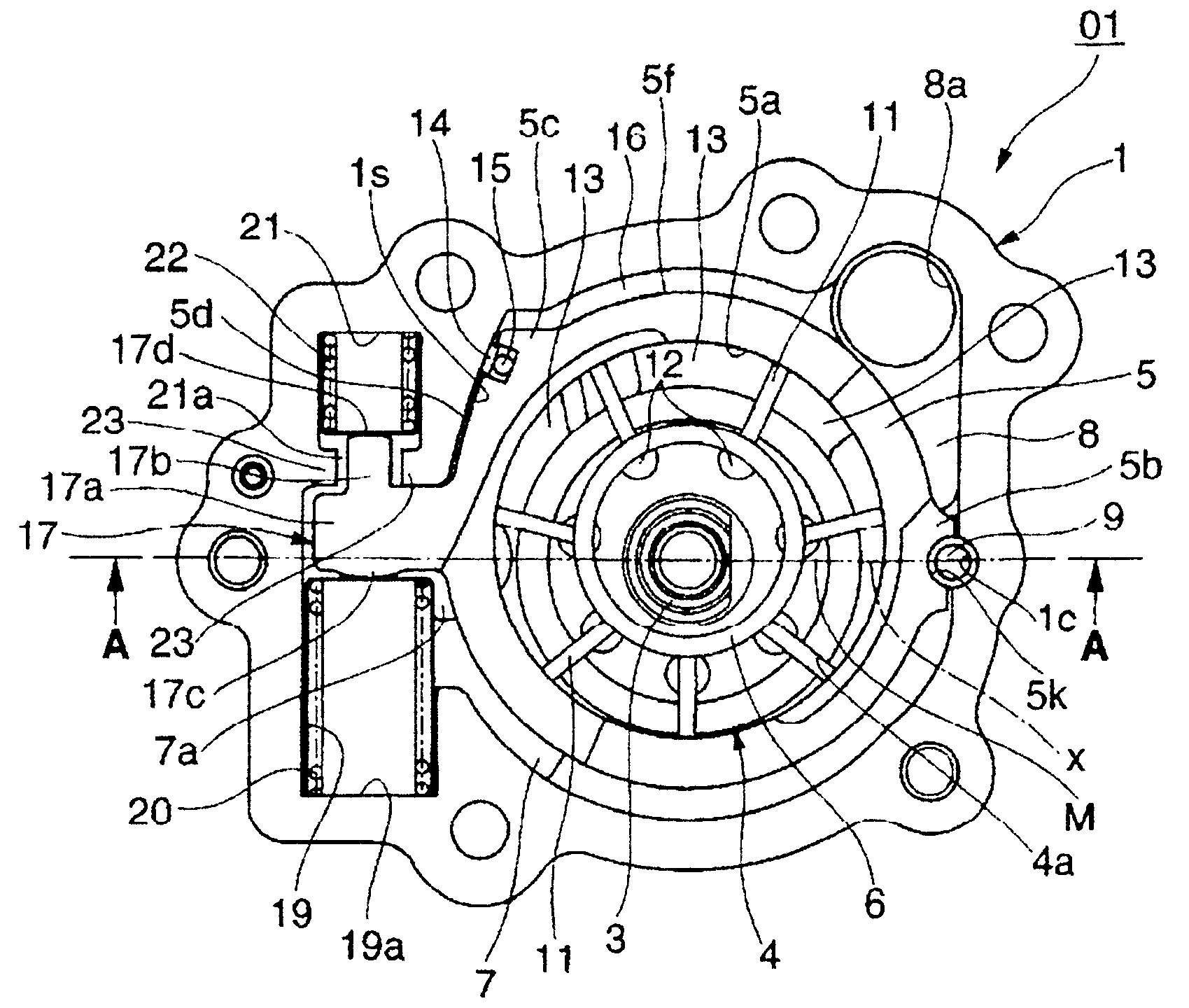
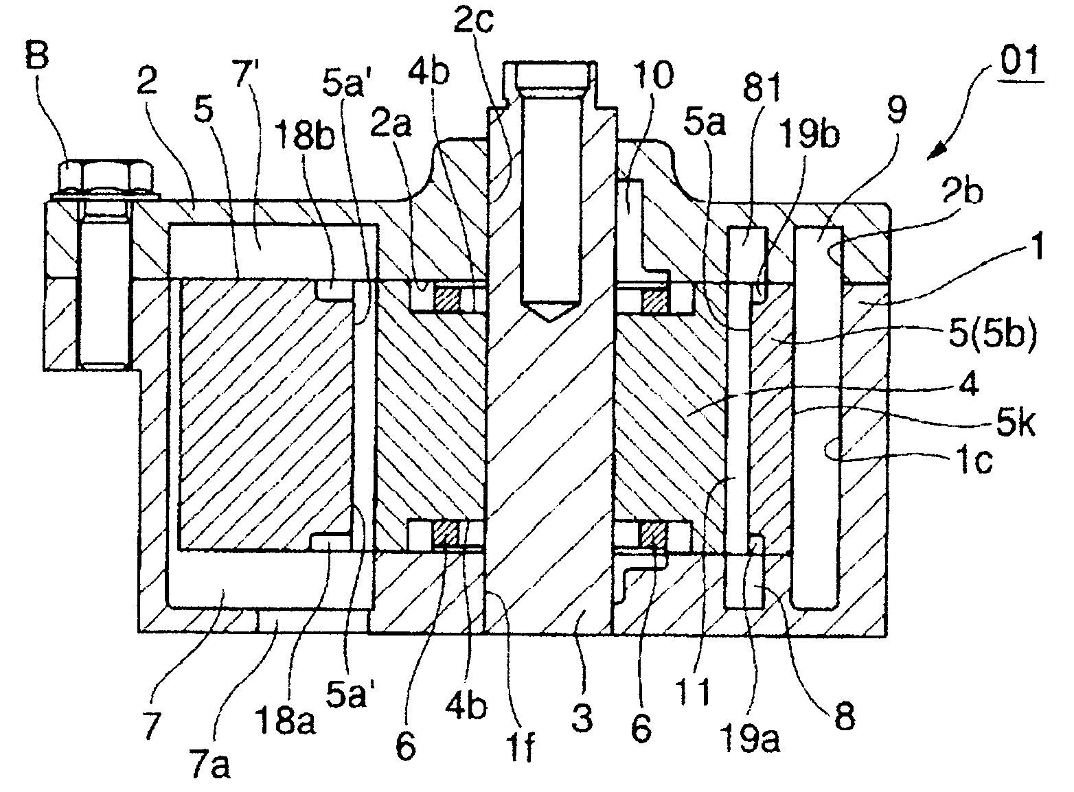
[0082] Such as Figure 1 ~ Figure 3 As shown, the variable displacement pump 01 includes: a bottomed cylindrical pump casing 1 provided at the front end of a cylinder block of an internal combustion engine and having one end opening closed by a cover member 2; The drive shaft 3 that is driven by the crankshaft of the engine, the rotor 4 that is rotatably accommodated inside the pump housing 1 and is connected to the drive shaft 3 at the center, and the movable shaft that is swingably arranged on the outer peripheral side of the rotor 4 The cam ring 5 and a pair of small-diameter vane rings 6 , 6 are slidably arranged on both side surfaces of the inner peripheral portion of the rotor 4 .

[0083] The above-mentioned pump casing 1 is integrally formed of an aluminum alloy material, such as Figure 4 As shown, since the concave bottom surface 1a slides on one axial side of the cam ring 5, the flatness and surface roughness of the bottom surface 1a are processed with high precisi...

no. 2 approach

[0193] Figure 20 The second embodiment is shown. The basic structure such as the pump structure is the same as that of the first embodiment, but two pilot oils are arranged above and below the pivot pin 9 in the figure to push the cam ring 5 so that the eccentricity increases. Room 16.

[0194] That is, assuming that the control oil chamber of the first embodiment is the first control oil chamber 16a, a substantially L-shaped groove 24 is formed in the lower portion of the pump housing 1 on the side of the pivot pin 9, and the groove 24 constitutes the second control oil chamber 16a. Control oil chamber 16b. In addition, a second sealing surface 24 a is formed at a lower portion of the groove 24 , and the second sealing surface 24 a is formed in an arc shape whose radius is centered on the axis of the pivot pin 9 .

[0195] On the other hand, a substantially triangular convex portion 25 is integrally provided at a portion of the cam ring 5 facing the inside of the groove 24...

no. 3 approach

[0201] Figures 21-29 The third embodiment showing the variable displacement pump 01 has some differences in structure from the variable displacement pump 01 of the first and second embodiments, but there are also common points, so details of the common points will be omitted. illustrate.

[0202] That is, the variable displacement pump 01 includes: a pump housing 111 having a pump housing chamber 113 with a U-shaped cross section; a cover member 112 for closing one end opening of the pump housing 111; The drive shaft 114 driven by the crankshaft of the engine; the rotor 115 which is rotatably accommodated in the pump housing chamber 113 and whose central part is connected to the drive shaft 114; The seven blades 116 that can advance and retreat freely in each slot 115a; the cam ring 117 that can be arranged eccentrically (swingable) relative to the rotation center of the rotor 115 inside the pump casing 111; A single coil spring 118 is a urging member that urges the cam rin...


PUM


Abstract

The invention provides a variable displacement pump, which can inhibit the energy consumption in the initial period of the oil discharge. The variable displacement pump has a pump structure which allows discharge of the oil guided to a plurality of pump chambers 13 from an inlet 7 according to the volumn variation of the pump chamber from an outlet 8; when the discharge pressure supplied into a control oil chamber 16 reaches to a first discharge pressure Pf, a cam ring moves a prescribed distance to a direction and when the discharge pressure becomes a second discharge pressure Ps higher than the first discharge pressure Pf, the cam ring moves further to the direction, thereby changing the discharge pressure of the pump. The first discharge pressure is set to the pressure lower than that opening a ball valve 46 through compression deformation of a valve spring 50 of an oil nozzle 30, thereby preventing the energy consumption when the discharge pressure is low.

Description

technical field [0001] The present invention relates to, for example, a variable displacement pump used in an internal combustion engine of an automobile, a lubrication system using the variable displacement pump, and an oil injector. Background technique [0002] As a conventional variable displacement pump, a variable displacement pump described in Patent Document 1 below is known. [0003] This conventional variable displacement pump includes a first spring that always exerts an elastic force on the cam ring, and a second spring that applies an elastic force in a direction opposite to the elastic force of the first spring when the cam ring moves beyond a predetermined pressure. The second spring changes the eccentric state of the cam ring in two stages by the relative elastic force of these two springs, thereby changing the discharge flow rate characteristic in two stages. [0004] In addition, the variable displacement pump releases the locked state of the valve timing ...

Claims


Application Information

Patent Timeline
Patent Type & Authority Applications(China)
IPC IPC(8): F04C14/22F04C29/02
CPCF04C2/3441F04C14/226
Inventor 渡边靖大西秀明
Owner HITACHI AUTOMOTIVE SYST LTD
Why Eureka
Try Eureka