Protection gas controlling device and welding device

A shielding gas and control device technology, which is applied in welding equipment, flow control of electrical devices, manufacturing tools, etc., can solve the problems of reducing the consumption of shielding gas and restraining the consumption of shielding gas, so as to achieve the goal of restraining consumption and restraining gas yield effect

Inactive Publication Date: 2010-10-06
SANSHA ELECTRIC MFG
View PDF1 Cites 18 Cited by
  • Summary
  • Abstract
  • Description
  • Claims
  • Application Information

AI Technical Summary

Problems solved by technology

However, in this structure, it is difficult to comprehensively suppress the consumption of shielding gas during the period or periods other than the postgas period from the start of pregas to the end of postgas.
In addition, in the conventional method, since the shielding gas is supplied in conjunction with the operation of the torch switch, it cannot be reduced if the welding current does not flow due to some reason such as a failure even though the torch switch is operated. Consumption of shielding gas

Method used


Image

  • Protection gas controlling device and welding device
  • Protection gas controlling device and welding device
  • Protection gas controlling device and welding device

Examples


Embodiment Construction

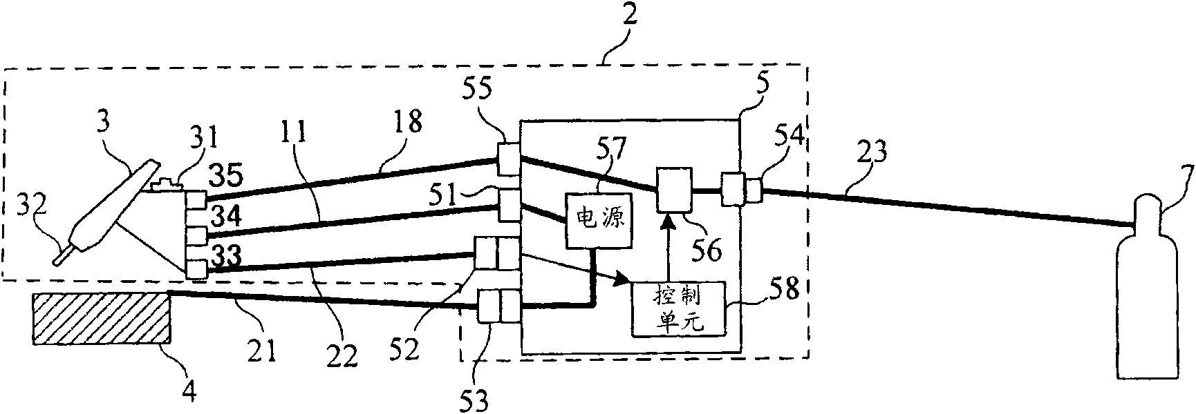
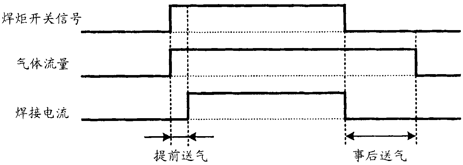
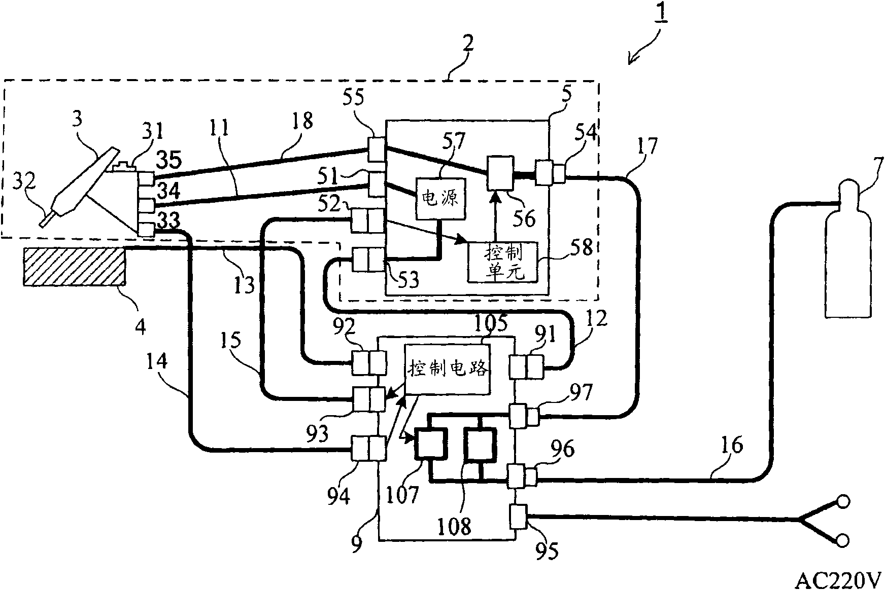
[0036] The present invention is applicable to a welding machine that performs gas-shielded arc welding and uses an inert gas as a shielding gas, and a gas control device connected to the welding machine. In the following description, an apparatus for performing TIG welding will be described as an example.

[0037] figure 2 It is a connection diagram of the welding system including the shielding gas control apparatus which concerns on embodiment of this invention.

[0038] Welding system 1 is in Figure 1A The welding device 2 shown is connected to a system of a shielding gas control device (hereinafter, simply referred to as a gas control device) 9 . The welding system 1 includes: a welding device 2 composed of a welding torch 3 and a welding machine 5 , a gas cylinder 7 serving as an inert gas supply source, and a gas control device 9 .

[0039] The power supply terminal 51 of the welding machine 5 and the terminal 34 of the torch switch are connected by the cable 11 . Th...


PUM


Abstract

Provided is a protection gas controlling device and welding device which comprehensively inhibits protection gas consumption in a plurality of periods. In a flow path of the protection gas, connecting a storage cylinder (7) and a welding torch (3), an gas valve (56) of a welding machine (56) and an gas valve (107) of a gas control device (9) are serially connected. A gas flow adjustor (108) whichhas the gas flow smaller than that in the gas valve (107) and is in parallel connection with the gas valve (107). In periods before gas feeding in advance and after gas feeding behindhand, gas valves(56, 107) are closed; in periods of gas feeding in advance, the crater period and gas feeding behindhand, the gas valve (56) is opened and the gas valve (107) is closed; and in the welding period (providing the welding current), gas valves (56, 107) are opened. Thereby, the protection gas consumption is inhibited in periods of gas feeding in advance and gas feeding behindhand.

Description

technical field [0001] The present invention relates to a shielding gas control device and a welding device for controlling the flow rate of shielding gas supplied to a welding machine. Background technique [0002] Arc welding is a welding method that utilizes the phenomenon of electric discharge (arc discharge) and connects the same metals. When the arc is generated at the beginning of arc welding, the temperature of the electrode rises rapidly, and when the arc is extinguished after the end of the arc welding, the temperature of the electrode gradually decreases. As described above, since the electrodes are at a high temperature from the beginning to the end of arc welding, the electrodes may be oxidized, resulting in deterioration of welding quality or occurrence of welding defects. Therefore, in order to protect electrodes and prevent welding defects, gas-shielded arc welding is popularized from the start of pre-flow before the start of arc welding to the end of after-...

Claims


Application Information

Patent Timeline
Patent Type & Authority Applications(China)
IPC IPC(8): B23K9/16G05D7/06
Inventor 大桥正博森本猛
Owner SANSHA ELECTRIC MFG
Why Eureka
Try Eureka