Supercharge Your Innovation With Domain-Expert AI Agents!

Bistable force and/or acceleration sensor

a technology of force sensor and acceleration sensor, which is applied in the direction of acceleration measurement, measurement devices, instruments, etc., can solve the problem of imposing much tougher requirements on the performance of devices

Inactive Publication Date: 2017-01-24
RAMOT AT TEL AVIV UNIV LTD
View PDF11 Cites 5 Cited by
  • Summary
  • Abstract
  • Description
  • Claims
  • Application Information

AI Technical Summary

Benefits of technology

Enables the measurement of forces and accelerations across a large dynamic range (tens of g) with high sensitivity and accuracy, allowing for continuous monitoring of small accelerations and variation over time, while eliminating contact issues and improving reliability.

Problems solved by technology

Although nowadays several MEMS-based inertial sensors were successfully commercialized and incorporated into consumer electronics products (mainly cell phones and computer games consoles) and in automotive industry (air bag crash sensors), micro accelerometers have not yet penetrated the market in the area of navigation, guidance and control applications, which impose much tougher requirements to the device performance.
In contrast to micro gyroscopes where alternatives to electromechanical devices are possible (ring laser gyroscope (LRG) and fiber optic gyroscope (FOG)), current accelerometers are still dominated by electromechanical sensors, mainly because no challenging alternative technology has succeeded (except for quartz resonators, which are used in the lower-grade tactical applications).

Method used


Image

  • Bistable force and/or acceleration sensor
  • Bistable force and/or acceleration sensor
  • Bistable force and/or acceleration sensor

Examples


Embodiment Construction

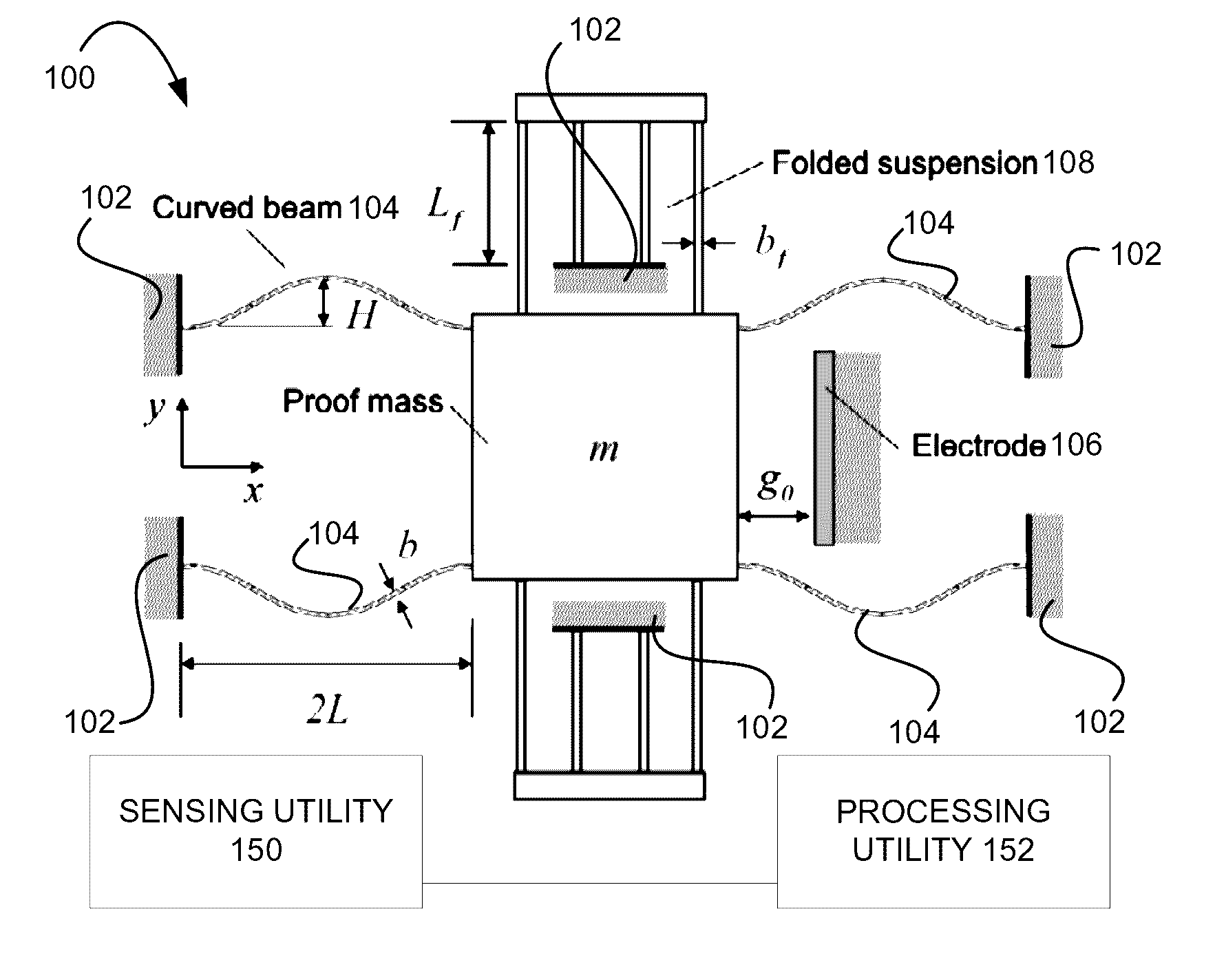
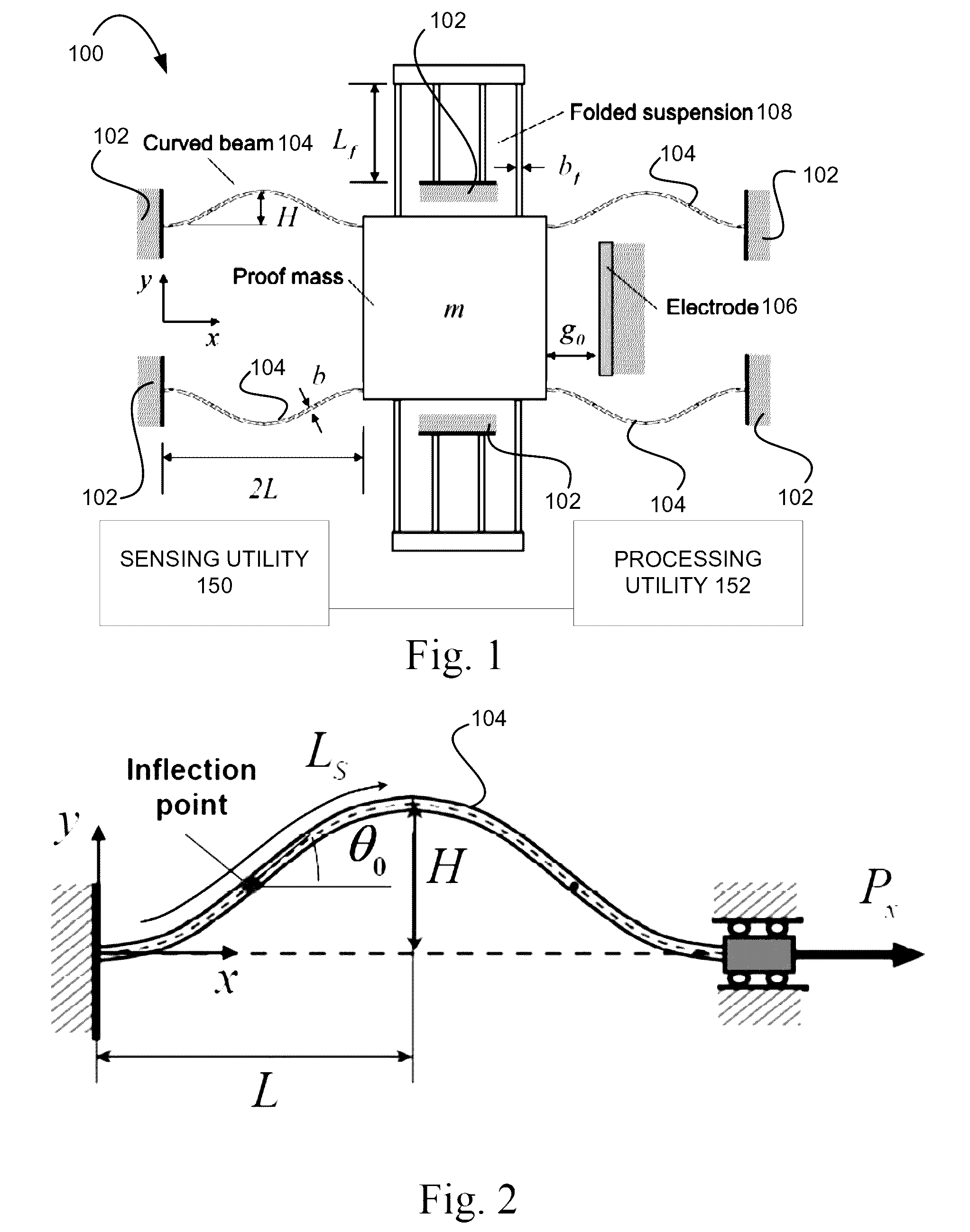
[0083]Referring now to FIG. 1, a schematic illustration exemplifies device 100 of the present invention. The device 100 includes a proof mass m attached / anchored to a base 102 (such as a substrate) by an elastic suspension, and actuated by an electrostatic force. The electrostatic force is implemented using an electrostatic actuator for moving the proof mass according to a selected time profile, such that a combination of forces applied to the proof mass by the elastic suspension and by the actuator generate a bistable condition in which a first region and a second region are present where a motion the proof mass is stable. Between these stable regions, an instability region is present, in which the motion of the proof mass is unstable. By monitoring a location of a stability boundary of at least one of the stable regions (generally the boundary between one of the stable regions and the unstable region) and determining a deviation thereof with respect to a predetermined location of ...


PUM


Abstract

A technique is provided for determining a force / acceleration acting on a proof mass of a bistable device. According to an aspect of the invention, the location of a boundary of one of the stable configurations of the device is monitored. The monitored location is compared to a predetermined location of the same boundary, said predetermined location corresponding to a condition in which the force / acceleration is absent, to detect a deviation of said location. The deviation is indicative of the force / acceleration and can be used to determine the force / acceleration. According to another aspect of the invention, the resonance frequency of the proof mass' oscillation in one of the stable regions is monitored, and compared to a predetermined resonance frequency the proof mass' oscillation in the same region corresponding to a condition in which the force / acceleration is absent, to determine a deviation of the resonance frequency due to the presence of force / acceleration. The deviation in the resonance frequency can be used to determine the force / acceleration.

Description

FIELD OF THE INVENTION[0001]This invention relates to force sensors, acceleration sensors, particularly to micro-scale accelerometers.REFERENCES[0002]The following references are considered to pertinent for the purpose of understanding the background of the invention:[0003][1] Li, B., Lu, D., Wang, W., 2000. “Open-Loop Operating Mode of Micromachined Capacitive Accelerometer”, Sensors and Actuators A, 79, pp. 219-223.[0004][2] Chae, J., Kulah, H., Najafi, K., 2005. “A MonolithicThree-Axis Micro-g Micromachined Silicon Capacitive Accelerometer”, J. Microelectromech. Syst., 14(2), pp. 235-242.[0005][3] Kim, H. C., Seok, S., Kim, I., Choi, S., Chun, K. 2005. “Inertial-Grade Out-of-Plane and In-Plane Differential Resonant Silicon Accelerometers (DRXLs)”, Proc. The 13th Int. Conf. on Solid-state Sensors, Actuators and Microsystems Transducers '05, Seoul, Korea, June, paper 1B5.1.[0006][4] Su, X.-P. S., Yang, H. S., 2001. “Single-Stage Microleverage Mechanism Optimization in a Resonant Ac...

Claims


Application Information

Patent Timeline
Patent Type & Authority Patents(United States)
IPC IPC(8): G01P15/08G01P15/097G01P15/125
CPCG01P15/0802G01P15/097G01P15/125G01P2015/0857
Inventor KRYLOV, VIACHESLAVAMIR, EMILRABANIM, SHILA
Owner RAMOT AT TEL AVIV UNIV LTD
Features
  • R&D
  • Intellectual Property
  • Life Sciences
  • Materials
  • Tech Scout
  • Unparalleled Data Quality
  • Higher Quality Content
  • 60% Fewer Hallucinations
Learn More