
Multilayer ceramic capacitor
a multi-layer ceramic and capacitor technology, applied in the direction of fixed capacitors, stacked capacitors, fixed capacitor details, etc., can solve the problems of reducing the reliability of multi-layer ceramic capacitors as a product, reducing the yield in a manufacturing process, and cracks at the boundary between multi-layer units and outer layer sections, so as to reduce or prevent cracks
- Summary
- Abstract
- Description
- Claims
- Application Information
AI Technical Summary
Benefits of technology
Problems solved by technology
Method used
Image

Examples
first preferred embodiment
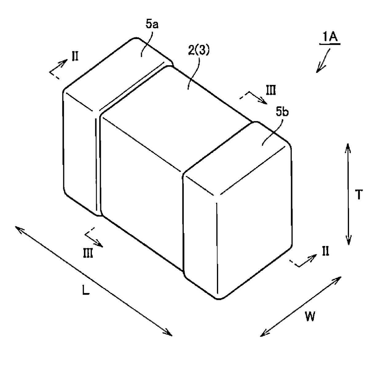
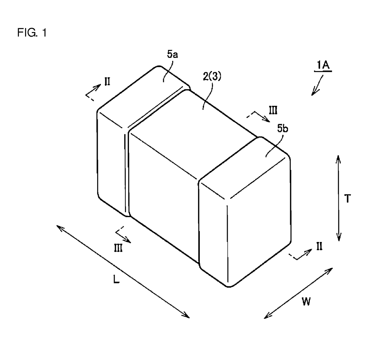
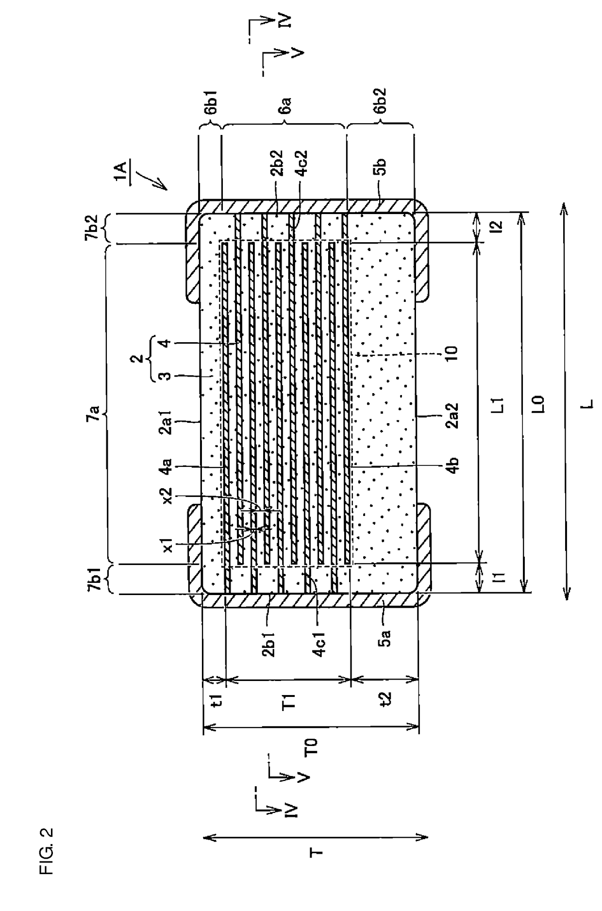
[0046]FIG. 1 is a schematic perspective view illustrating a multilayer ceramic capacitor 1A according to a first preferred embodiment of the present invention. FIGS. 2 and 3 are schematic sectional views taken along lines II-II and III-III, respectively, of FIG. 1. FIGS. 4 and 5 are schematic sectional views taken along lines IV-IV and V-V, respectively, of FIG. 2. The configuration of the multilayer ceramic capacitor 1A of the first preferred embodiment will first be described below with reference to FIGS. 1 through 5.
[0047]As shown in FIGS. 1 through 5, the multilayer ceramic capacitor 1A is an electronic component preferably having a rectangular or substantially rectangular parallelepiped shape and including a body 2 and first and second outer electrodes 5a and 5b, which define a pair of outer electrodes.
[0048]As shown in FIGS. 2 through 5, the body 2 preferably has a rectangular or substantially rectangular parallelepiped shape and includes ceramic dielectric layers 3 and inner ...
second preferred embodiment
[0155]FIG. 13 is a schematic perspective view illustrating a multilayer ceramic capacitor 1B according to a second preferred embodiment of the present invention. FIGS. 14 and 15 are schematic sectional views taken along lines XIV-XIV and XV-XV, respectively, of FIG. 13. The configuration of the multilayer ceramic capacitor 1B of the second preferred embodiment will be described below with reference to FIGS. 13 through 15.
[0156]As shown in FIGS. 13 through 15, the multilayer ceramic capacitor 1B of the second preferred embodiment is different from the multilayer ceramic capacitor 1A of the first preferred embodiment in the configuration of the thickness-direction second outer layer section 6b2, for example. More specifically, the thickness-direction second outer layer section 6b2 of the multilayer ceramic capacitor 1B includes an inner portion 6b21 disposed adjacent to the thickness-direction inner layer section 6a and an outer portion 6b22 which is disposed adjacent to the inner por...
modified example
[0193]FIGS. 16 and 17 are schematic sectional views illustrating a multilayer ceramic capacitor 1C according to a modified example of the second preferred embodiment of the present invention. The cross sections shown in FIGS. 16 and 17 correspond to those shown in FIGS. 14 and 15, respectively. The multilayer ceramic capacitor 1C of this modified example will be described below with reference to FIGS. 16 and 17.
[0194]As shown in FIGS. 16 and 17, the multilayer ceramic capacitor 1C of this modified example is different from the multilayer ceramic capacitor 1B of the second preferred embodiment only in the configuration of the outer portion 6b22 of the thickness-direction second outer layer section 6b2. More specifically, the outer portion 6b22 partially curves and protrudes toward the inner portion 6b21 of the thickness-direction second outer layer section 6b2.
[0195]This will be discussed more specifically. As shown in FIG. 16, a portion of the outer portion 6b22 which corresponds to...
PUM
| Property | Measurement | Unit |
|---|---|---|
| thickness | aaaaa | aaaaa |
| thickness | aaaaa | aaaaa |
| thickness | aaaaa | aaaaa |
Abstract
Description
Claims
Application Information