Fluid-filled vibration damping device

a technology of vibration damping device and fluid filling, which is applied in the direction of shock absorbers, machine supports, mechanical devices, etc., can solve the problems of limited deformation or displacement of movable parts, and achieve the effect of reducing the free length allowed, reducing or avoiding

Active Publication Date: 2014-11-06
SUMITOMO RIKO CO LTD
View PDF3 Cites 3 Cited by
  • Summary
  • Abstract
  • Description
  • Claims
  • Application Information

AI Technical Summary

Benefits of technology

[0046]With the present invention, the wall inner surfaces of the housing space to be struck by the movable member have the rubber buffer arranged so as to be covered thereby, and the movable member is partially grasped in the thickness direction between the wall inner surfaces of the housing space via the rubber buffer. By so doing, in addition to the energy attenuation action by the internal friction and the like of the rubber buffer, by reducing the free length allowed for the deformation and displacement of the movable member, the striking noise that occurs with the contacting of the movable member on the wall inner surface of the housing space is reduced or avoided.

Problems solved by technology

Furthermore, since the movable member is partially grasped in the thickness direction between the wall inner surfaces of the housing space, the deformation or displacement of the movable member is limited by the wall inner surface of the housing space.

Method used


Image

  • Fluid-filled vibration damping device
  • Fluid-filled vibration damping device
  • Fluid-filled vibration damping device

Examples


first embodiment

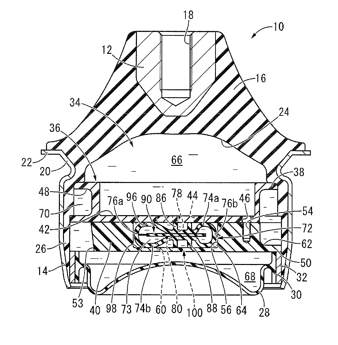
[0076]FIG. 1 shows an automobile engine mount 10 as the fluid-filled vibration damping device constituted according to the present invention. The engine mount 10 has a constitution for which a first mounting member 12 and a second mounting member 14 are elastically connected by a main rubber elastic body 16, and the first mounting member 12 is attached to a power unit (not shown), and the second mounting member 14 is attached to a vehicle body (not shown). With the description below, the vertical direction means the vertical direction in FIG. 1 as a rule.

[0077]In more specific detail, the first mounting member 12 is a highly rigid member formed using an iron or aluminum alloy or the like, and exhibits overall a small diameter, roughly circular block shape, for which the upper part has a roughly round column shape, and the lower part is roughly a reverse-facing conic trapezoid that gradually shrinks facing downward. Also, on the first mounting member 12, a bolt hole 18 is formed that...

third embodiment

[0132]FIG. 13 shows an automobile engine mount 130 as the fluid-filled vibration damping device constituted according to the present invention. The engine mount 130 has a constitution with which rubber buffer 132 is arranged in the housing space 64 of the partition member 36.

[0133]The rubber buffer 132 is a hollow band shaped tube integrally equipped with the pair of facing plate portions 74a and 74b and the pair of side plate portions 76a and 76b, and a movable film 134 as the movable member integrally projects from one side plate portion 76a. The movable film 134 has a roughly rectangular plate shape, and overall is formed with roughly fixed thickness dimensions and width dimensions.

[0134]Furthermore, the upper elastic projection 86 projecting upward is integrally formed on the facing plate portion 74a of the rubber buffer 132, and the lower elastic projection 88 projecting downward is integrally formed on the facing plate portion 74b. With this embodiment, one each of the upper e...

fourth embodiment

[0136]FIG. 14 shows an automobile engine mount 140 as the fluid-filled vibration damping device constituted according to the present invention. The engine mount 140 has a constitution with which rubber buffer 142 is arranged in the housing space 64.

[0137]The rubber buffer 142 is a hollow band shaped tube integrally equipped with the pair of facing plate portions 74a and 74b and the pair of the side plate portions 76a and 76b, and the movable film 134 integrally projects from one side plate portion 76a. The movable film 134 has a roughly rectangular plate shape, and overall has roughly fixed thickness dimensions and width dimensions.

[0138]Furthermore, an upper elastic projection 144 projecting downward is integrally formed on the facing plate portion 74a of the rubber buffer 142, and a lower elastic projection 146 projecting upward is integrally formed on the facing plate portion 74b. With this embodiment, two each of the upper elastic projections 144 and the lower elastic projection...


PUM


Abstract

A fluid-filled vibration damping device including: first and second mounting members elastically connected by a main rubber elastic body; a partition member supported by the second mounting member; a pressure-receiving chamber and an equilibrium chamber disposed on either side of the partition member; a housing space formed within the partition member; a plate-shaped movable member arranged in the housing space with liquid pressures of the pressure-receiving chamber and the equilibrium chamber applied to the respective faces of the movable member; and a rubber buffer arranged on wall inner surfaces of the housing space to be struck by the movable member. The movable member is grasped partially in a thickness direction between the wall inner surfaces of the housing space via the rubber buffer at surfaces facing the wall inner surfaces of the housing space.

Description

INCORPORATED BY REFERENCE[0001]The disclosures of Japanese Patent Application Nos. 2012-132573 filed on Jun. 12, 2012 and 2012-132574 filed on Jun. 12, 2012, each including the specification, drawings and abstract is incorporated herein by reference in its entirety. This is a Continuation of International Application No. PCT / JP2013 / 003512 filed on Jun. 4, 2013.BACKGROUND OF THE INVENTION[0002]1. Field of the Invention[0003]The present invention relates to a fluid-filled vibration damping device used for automobile engine mounts and the like.[0004]2. Description of the Related Art[0005]From the past, vibration damping devices have been known which are interposed between members constituting a vibration transmission system, and for which those members have a mutual vibration damping connection and vibration damping support, and as one type of vibration damping device, fluid-filled vibration damping devices are also known that exhibit a vibration damping effect based on the fluid flow ...

Claims


Application Information

Patent Timeline
Patent Type & Authority Applications(United States)
IPC IPC(8): F16F13/08F16F13/10
CPCF16F13/08F16F13/10F16F13/106
Inventor KANAYA, TOMOHIRO
Owner SUMITOMO RIKO CO LTD
Why Eureka
Try Eureka