
Elastic yarn winding system and elastic yarn winding machine and elastic yarn winding method

An elastic yarn and winding machine technology, which is applied in the field of elastic yarn winding, can solve the problems of difficult setting of distance X, inability to stabilize the turning point, and difficulty in free length, etc.

Active Publication Date: 2009-08-05
TMT MACHINERY INC
View PDF9 Cites 1 Cited by
  • Summary
  • Abstract
  • Description
  • Claims
  • Application Information

AI Technical Summary

Problems solved by technology

Therefore, the distance X is difficult to be precisely set and the free length (L+X) downstream of the traversing device is difficult to be stabilized
Therefore, when the elastic yarn Y is wound into a package 3, its turning point cannot be stabilized, which causes the crimping of the package and the irregularity of the end surface.

Method used

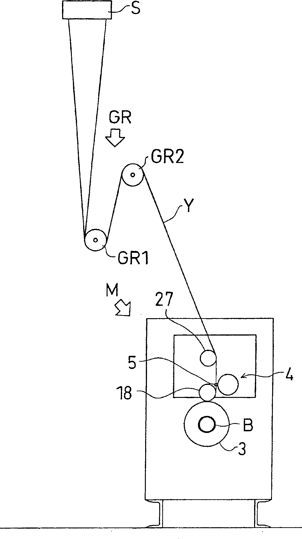
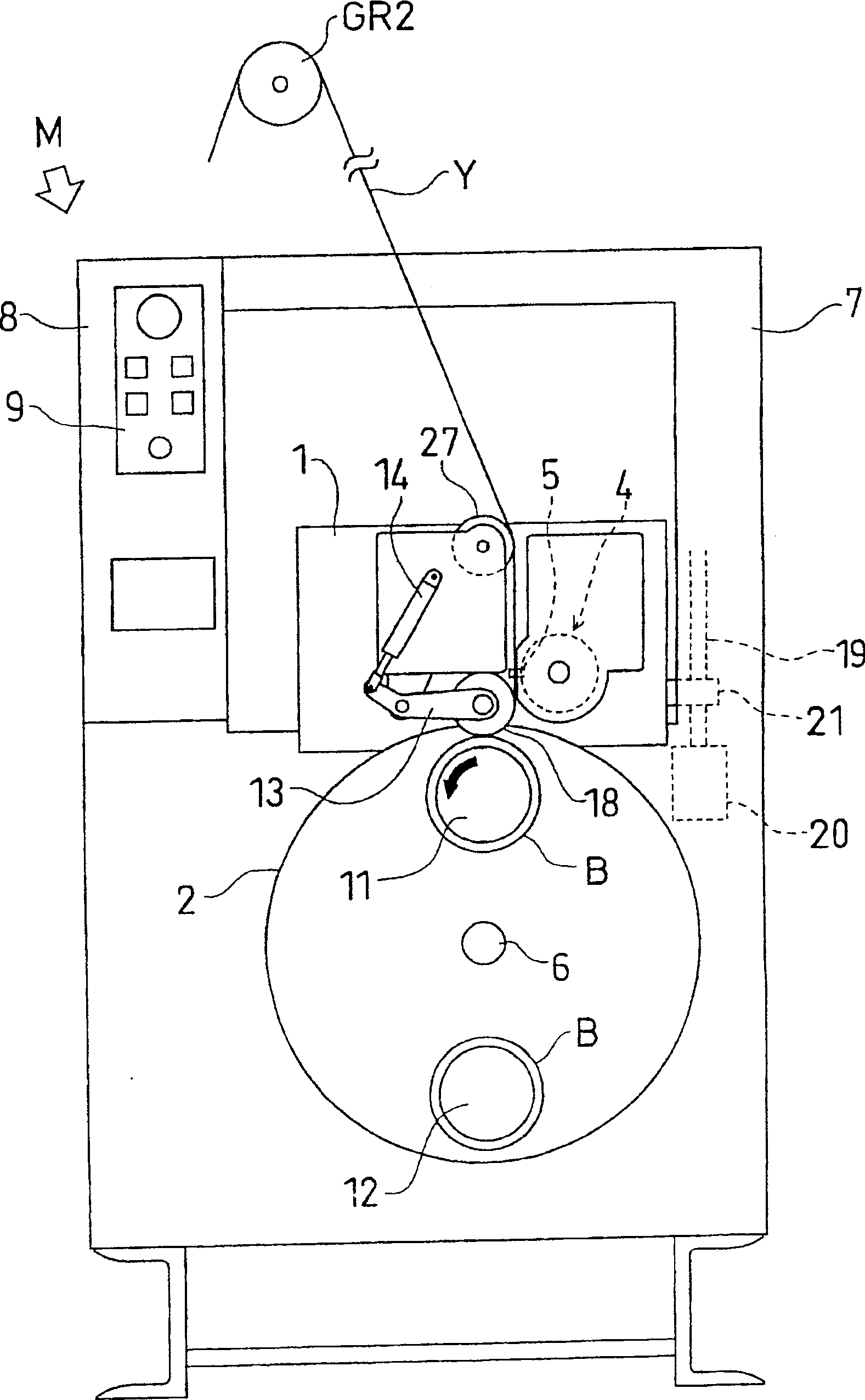
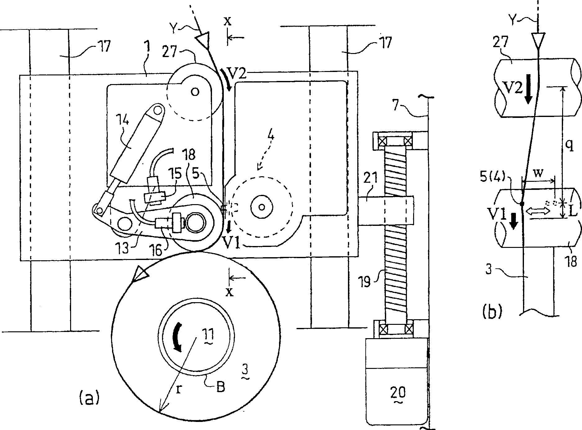

Image

  • Elastic yarn winding system and elastic yarn winding machine and elastic yarn winding method
  • Elastic yarn winding system and elastic yarn winding machine and elastic yarn winding method
  • Elastic yarn winding system and elastic yarn winding machine and elastic yarn winding method

Examples


Embodiment Construction

[0030] Embodiments of the present invention will be described.

[0031] figure 1 The entire elastic yarn winding system is shown. The elastic yarn winding system comprises a monofilament spinning machine S, a guide roller for receiving and feeding an elastic monofilament yarn Y such as a polyurethane monofilament yarn spun from the monofilament spinning machine S For GR, and Elastic Yarn Winder M. The guide roller pair GR includes an upstream guide roller GR1 and a downstream guide roller GR2. The upstream guide roller GR1 receives the elastic monofilament yarn Y from the monofilament spinning machine S and determines the quality of the elastic yarn Y. The downstream guide roller GR2 is arranged downstream of the guide roller GR1 in the direction of yarn travel and changes the direction of yarn travel.

[0032] figure 2 The overall structure of the elastic yarn winding machine M is shown. The elastic yarn winding machine winds the elastic yarn Y fed from the guide roll...


PUM


Abstract

PROBLEM TO BE SOLVED: To provide a winder for a resilient yarn capable of suppressing low the residual shrinkage ratio when a roll is formed and establishing a good package shape. SOLUTION: The winder for the resilient yarn is equipped with a contacting roller 18 installed downstream in the yarn advancing direction with respect to a godet roller couple and contacting with the peripheral surface of a roll 3 to be prepared while the resilient yarn Y is being taken up. A traversing device 4 is installed upstream of the contacting roller 18 about the yarn advancing direction. The resilient yarn Y put in the traverse motion by the traversing device 4 is taken up on the roll 3 being prepared through the contacting roller 18. A feed roller 27 is installed upstream of the traversing device 4 about the yarn advancing direction (between the godet roller and the traversing device 4), and the rotating speeds of the feed roller 27 and the contacting roller 18 are controlled so that the peripheral linear speed V2 of the feed roller 27 becomes higher than that V1 of the contacting roller 18. COPYRIGHT: (C)2005,JPO&NCIPI

Description

technical field [0001] The invention relates to the construction of an elastic yarn winding system and an elastic yarn winding machine for winding elastic yarn, such as a monofilament spinning machine, onto a bobbin and producing so-called packages Spun polyurethane monofilament yarn. The invention also relates to an elastic yarn winding method. Background technique [0002] Generally, elastic yarns such as polyurethane monofilament yarns have very high elasticity and very low stiffness. In the case of winding such an elastic yarn, if the elastic yarn is wound under a higher tension state, the elastic yarn is wound under a stretched state, resulting in a high residual shrinkage of the elastic yarn . Therefore, the quality of the package deteriorates. For example, the shape of the package becomes defective and the unwinding process of the yarn from the package cannot be performed correctly. [0003] Figure 7 (a) shows that corresponding to Patent Document 1 figure 2 o...

Claims


Application Information

Patent Timeline
Patent Type & Authority Patents(China)
IPC IPC(8): B65H54/28B65H54/52B65H59/18D01D7/00
CPCB65H54/2869D01D7/00
Inventor 桥本欣三
Owner TMT MACHINERY INC
Learn More