Drawing mouth

A yarn feeder and yarn technology, used in spinning machines, open-end spinning machines, and continuously wound spinning machines, etc., can solve the problems of rotor speed limitation, high surface temperature, etc., and achieve effective wear protection, Improve heat dissipation, good heat dissipation effect

Active Publication Date: 2016-05-25
RIETER INGOLSTADT GMBH
View PDF10 Cites 2 Cited by
  • Summary
  • Abstract
  • Description
  • Claims
  • Application Information

AI Technical Summary

Problems solved by technology

However, the surfaces of the nozzle funnel in contact with the extracted yarn still generate extremely high surface temperatures, and the thermal load on the nozzle often limits the rotor speed

Method used


Image

  • Drawing mouth
  • Drawing mouth
  • Drawing mouth

Examples


Embodiment Construction

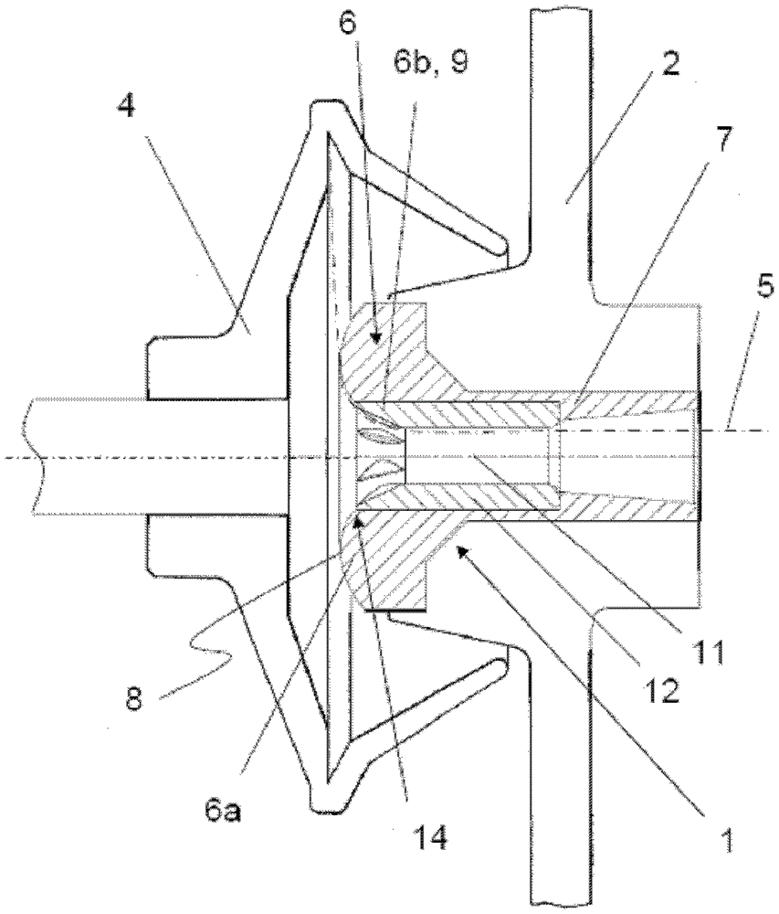
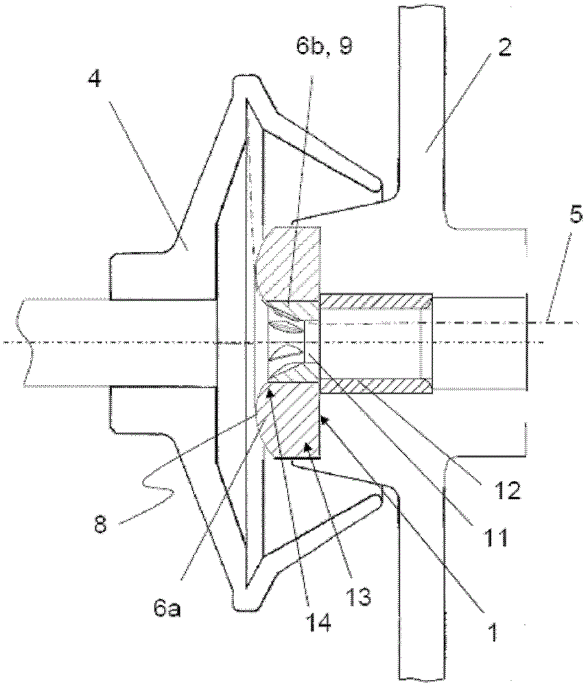
[0027] figure 1 The illustrated spinning nozzle 1 according to the invention is fixed in a known manner in a shroud 2 of a rotor housing, not shown here. Yarn drawing mouth 1 is used for guiding the yarn 5 made on the spinning rotor 4 to make it turn around, and here the yarn is represented by a dotted line. Wherein, the rotational speed of the spinning rotor 4 reaches up to 150,000 revolutions per minute, and the drawing speed of the finished yarn 5 is, for example, 250 m / min. When the rotor 4 rotates, the yarn 5 is moved around the surface of the yarn drawing mouth 1 in the manner of crank transmission.

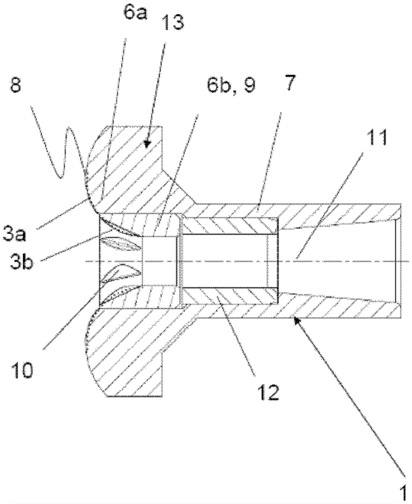
[0028] In this embodiment, the yarn drawing nozzle 1 is composed of the yarn drawing nozzle funnel 6 and the yarn drawing nozzle shaft 7, the yarn 5 turns on the yarn drawing nozzle funnel, and the yarn drawing nozzle shaft is used to fix the yarn drawing nozzle 1 on the shield of the spinning device 2 within. Due to the uninterrupted contact with the high-speed circular...


PUM


Abstract

A suction nozzle for air spinning apparatus (1), having a suction nozzle funnel for making a yarn (5) steering during the drawing process (6), the sphering nozzle funnel comprises a yarn steering area (3). The yarn nozzle funnel (6) specifically comprises two parts, i.e., a first region comprising the yarn steering area (3) (3a) of the outer portion (6a) and a second region (3b) comprising the yarn steering region (3) of the inner portion (6b). The two portions (6a, 6b) are composed of different materials and / or at least in the yarn steering zone (3) of the region (3a, 3b) is provided with different coatings, or, the two portions (6a, 6b) of which only one portion has a coating.

Description

technical field [0001] The invention relates to a yarn draw nozzle for an air spinning device, the yarn draw nozzle comprising a yarn draw nozzle funnel for deflecting a finished yarn during the yarn draw process, the yarn draw nozzle funnel containing a yarn deflection zone. Background technique [0002] There are various yarn drawing nozzles for air spinning machines in the prior art. These yarn drawing nozzles are fixed in the yarn drawing channel of the air spinning device, and are used for guiding and turning the yarn made on the spinning rotor during the yarn drawing process. The yarn drawing nozzle is in continuous contact with the yarn it draws during the working process, which will cause the yarn drawing nozzle to heat up severely, especially when the rotor rotates at a high speed and the yarn drawing speed is high. If the heat cannot be effectively dissipated, the high temperature generated by this part of the heat will damage the yarn, resulting in yarn breakage,...

Claims


Application Information

Patent Timeline
Patent Type & Authority Patents(China)
IPC IPC(8): D01H13/04D01H4/02
CPCD01H4/40
Inventor J·舍默尔E·施尼勒
Owner RIETER INGOLSTADT GMBH
Why Eureka
Try Eureka