
Pressure body arrangement for a claw coupling
a technology of pressure body and claw coupling, which is applied in the direction of yielding coupling, interengaging clutches, and clutches, etc., can solve the problems of restricting construction, significant and undesired deformation of the ring element of the pressure body ring, and uneven pressure distribution, etc., to achieve simple construction, high torque, and the effect of simple construction
- Summary
- Abstract
- Description
- Claims
- Application Information
AI Technical Summary
Benefits of technology
Problems solved by technology
Method used
Image

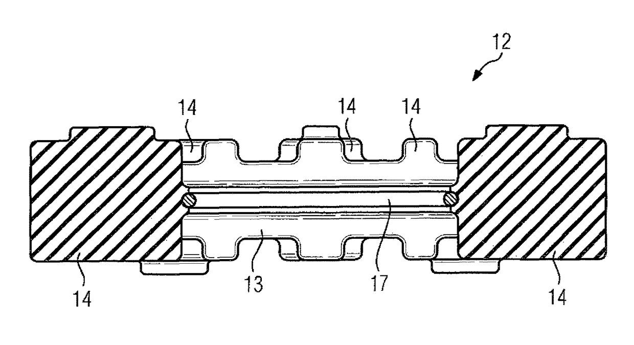
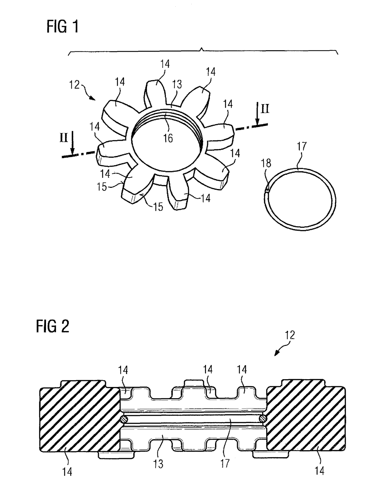
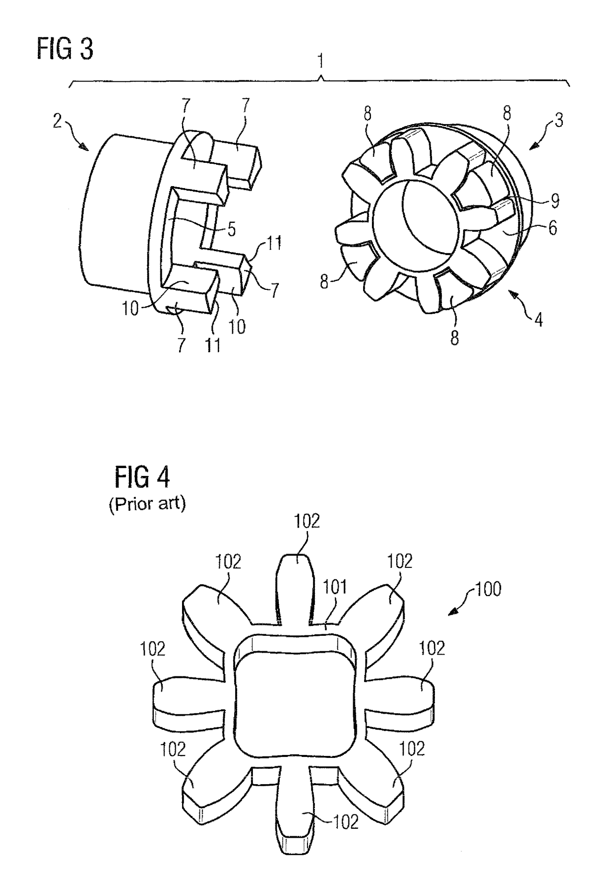
Examples
Embodiment Construction
[0019]Throughout all the figures, same or corresponding elements may generally be indicated by same reference numerals. These depicted embodiments are to be understood as illustrative of the invention and not as limiting in any way. It should also be understood that the figures are not necessarily to scale and that the embodiments may be illustrated by graphic symbols, phantom lines, diagrammatic representations and fragmentary views. In certain instances, details which are not necessary for an understanding of the present invention or which render other details difficult to perceive may have been omitted.
[0020]Turning now to the drawing, and in particular to FIG. 3, there is shown a perspective view of a claw coupling, generally designated by reference numeral 1. The claw coupling 1 serves to transmit torque between two shafts aligned with one another and includes, when assembled, as main components two coupling elements 2, 3 disposed axially opposite one another with aligning long...
PUM
 Abstract
Description
Claims
Application Information