Compound planetary friction drive

a technology of friction drive and compound planetary, which is applied in the direction of friction gearing, belt/chain/gearing, friction gearing, etc., can solve the problems of failure limits failure of com-pact high-force friction drive, and difficulty in design or implementation of existent compound planetary friction drive. achieve high gear ratio and transmit high torqu

Active Publication Date: 2017-06-29
TECH UNIV DELFT
View PDF1 Cites 7 Cited by
  • Summary
  • Abstract
  • Description
  • Claims
  • Application Information

AI Technical Summary

Benefits of technology

[0015]It is therefore an object of the invention to provide a compound planetary friction drive which makes possible to provide at the same time a high gear ratio and the capability to transmit high torques.

Problems solved by technology

There are difficulties within the design or implementation of existent compound planetary friction drives.
Due to steel having a high stress / strain relationship, a single 1 / 1000th of a millimeter out of tolerance can result in that the compressing force will amount in the hundreds or thousands of Newtons of force, which exceeds the failure limits of the material.
When taken together, both problems mean that a com-pact high-force friction drive is not manufacturable.
It is impossible to guarantee high (but not too high) contact forces between the cylinder shaped sun wheel and planetary wheels.

Method used


Image

  • Compound planetary friction drive
  • Compound planetary friction drive
  • Compound planetary friction drive

Examples


second embodiment

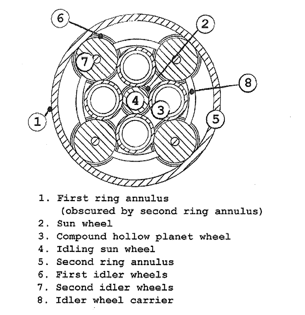
[0027]In another favorable second embodiment of the com-pound planetary friction drive according to the invention, first idling wheels are imposed between the first part of the planetary wheels and the first ring annulus, and second idling wheels are imposed between the second part of the planetary wheels and the second ring annulus. The idling wheels create in conjunction with the first and second sun wheels a triangular suspension of the hollow planetary wheels. This arrangement prevents the hollow planetary wheels from advancing or retreating relative to the other wheels. To support their function, it is preferable that the first idling wheels and the second idling wheels are axially aligned. For this purpose, advantageously the first idling wheels and the second idling wheels are mounted on a carrier structure which allows the first and second idling wheels to rotate freely, but remain in axial alignment.

[0028]The invention will hereinafter be further elucidated with reference t...

first embodiment

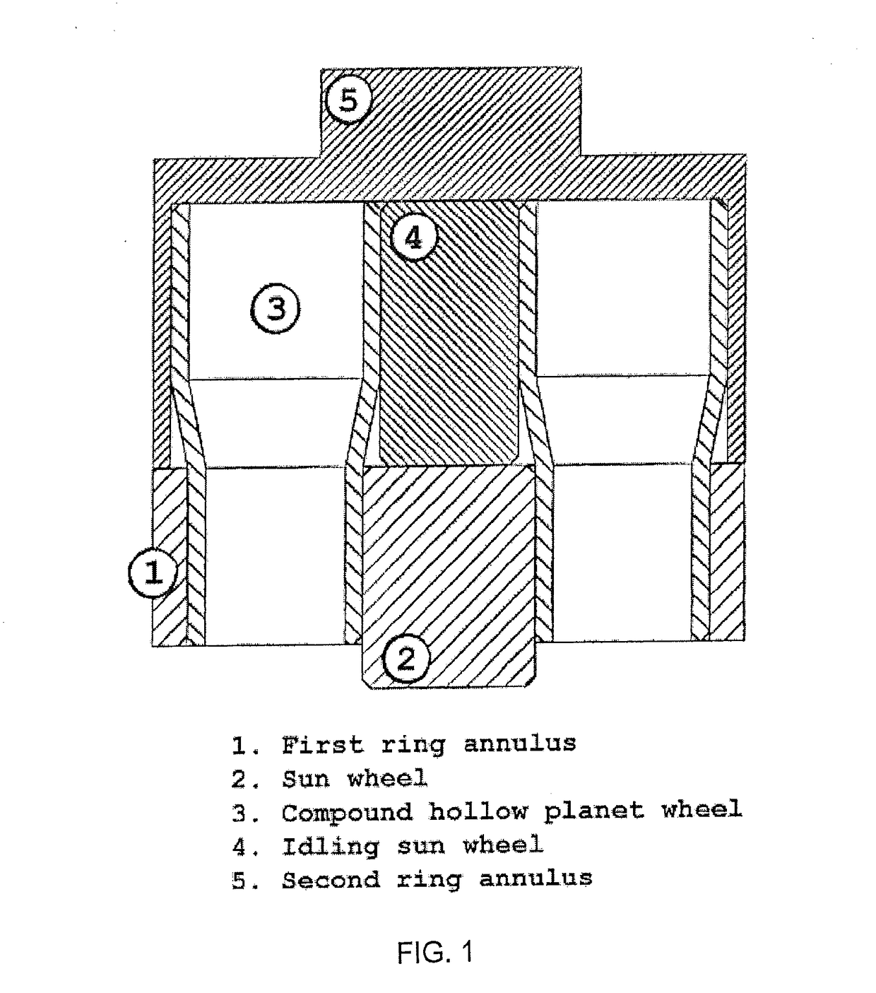
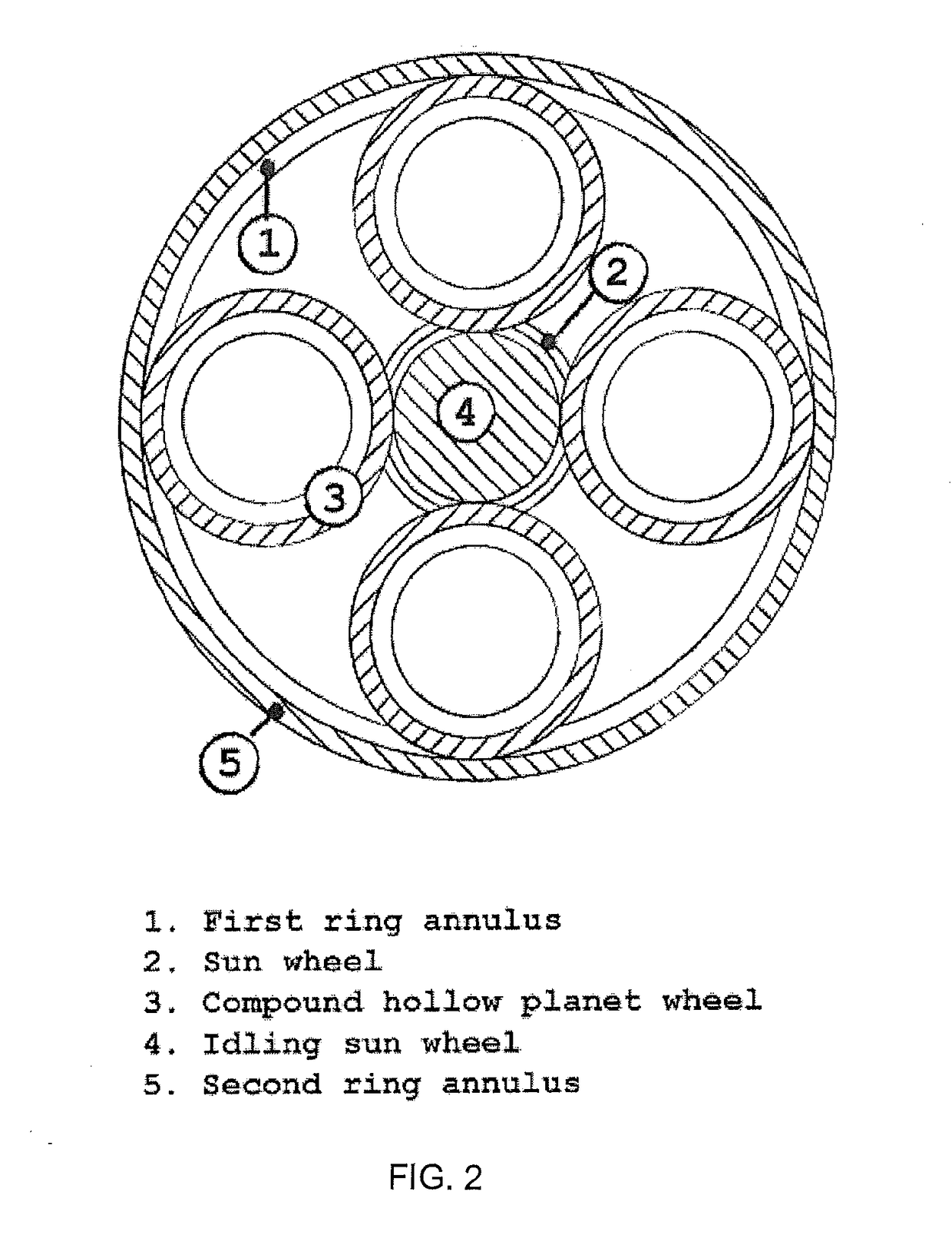
[0034]FIG. 3 relating to the first embodiment shows that when the first sun wheel 2 is turned, the compound planetary wheels 3 roll along the inner wall of the first ring annulus 1. This is exactly as in standard epicyclic transmission. While the planetary wheels 3 are ‘rolling’ along the inner wall of the first ring annulus 1, they are also rotating about their individual axis. Because of the small step present in the radius of the planetary wheels 3 (FIG. 1 shows clearly that the top half of the planetary wheels is of a slightly larger diameter than that of the lower half), the tangential velocity of the ‘output’ or up-per portion of the compound planetary wheels 3 is slightly higher than that of the ‘input’ or lower portion of said planetary wheels 3. This relation can also be reversed so as to have the tangential velocity of the input larger than that of the output by making the diameter of the top half of the planetary wheels slightly smaller than that of the lower half.

[0035]T...


PUM


Abstract

Compound planetary friction drive comprising an input shaft driving a sun wheel, wherein said sun wheel engages planetary wheels, which planetary wheels are arranged with a first part having a first radius and a second part having a second radius that differs from the first radius, and where-in a ring cylinder is provided that is engaged by the planetary wheels such that the sun wheel is in frictional engagement with the first part of the planetary wheels and the ring cylinder is in frictional engagement with the second part of the planetary wheels, wherein the planetary wheels are hollow and compressible.

Description

CROSS-REFERENCE TO RELATED APPLICATIONS[0001]This application is a continuation of the filing of Patent Cooperation Treaty Application No. PCT / NL2015 / 050607, filed on Sep. 2, 2015, which claims priority to Netherlands Patent Application No. 2013496, filed on Sep. 19, 2014, and the specifications and claims thereof are incorporated herein by reference.STATEMENT REGARDING FEDERALLY SPONSORED RESEARCH OR DEVELOPMENT[0002]Not Applicable.THE NAMES OF PARTIES TO A JOINT RESEARCH AGREEMENT[0003]Not Applicable.INCORPORATION BY REFERENCE OF MATERIAL SUBMITTED ON A COMPACT DISC[0004]Not Applicable.STATEMENT REGARDING PRIOR DISCLOSURES BY THE INVENTOR OR A JOINT INVENTOR[0005]Not Applicable.COPYRIGHTED MATERIAL[0006]Not Applicable.BACKGROUND OF THE INVENTION[0007]Field of the Invention (Technical Field)[0008]The present invention relates to a compound planetary friction drive comprising a first sun wheel, wherein said first sun wheel engages planetary wheels, which planetary wheels are arrange...

Claims


Application Information

Patent Timeline
Patent Type & Authority Applications(United States)
IPC IPC(8): F16H13/06
CPCF16H13/06F16H13/10
Inventor SCHORSCH, JACK FLOYD
Owner TECH UNIV DELFT
Why Eureka
Try Eureka