Deadlock arrangement for locks

a deadlock and lock technology, applied in the field of locks, can solve the problems of cumbersome locks, not particularly adaptable, and not providing a good drive ratio, and requiring significant torqu

Inactive Publication Date: 2006-01-10
INOVEC
View PDF12 Cites 22 Cited by
  • Summary
  • Abstract
  • Description
  • Claims
  • Application Information

AI Technical Summary

Benefits of technology

[0009]An advantage of such an arrangement is that by using a rack and pinion to drive the bolt between its retracted and extended positions. A small diameter pinion gear may be used. This increase the drive ratio thereby maximising torque transferred from the drive to the bolt.
[0011]In preference said pinion gear includes a second arm adapted to abut against a shoulder of said rack to from a mechanical stop. This prevents the lock from being overdriven.

Problems solved by technology

However, these locks are cumbersome and are not particularly adaptable for locks of the type that can be driven by two independent means, such as key and electric motor operation.
Further they do not provide a good drive ratio requiring significant torque to operate the lock.

Method used


Image

  • Deadlock arrangement for locks
  • Deadlock arrangement for locks
  • Deadlock arrangement for locks

Examples


Embodiment Construction

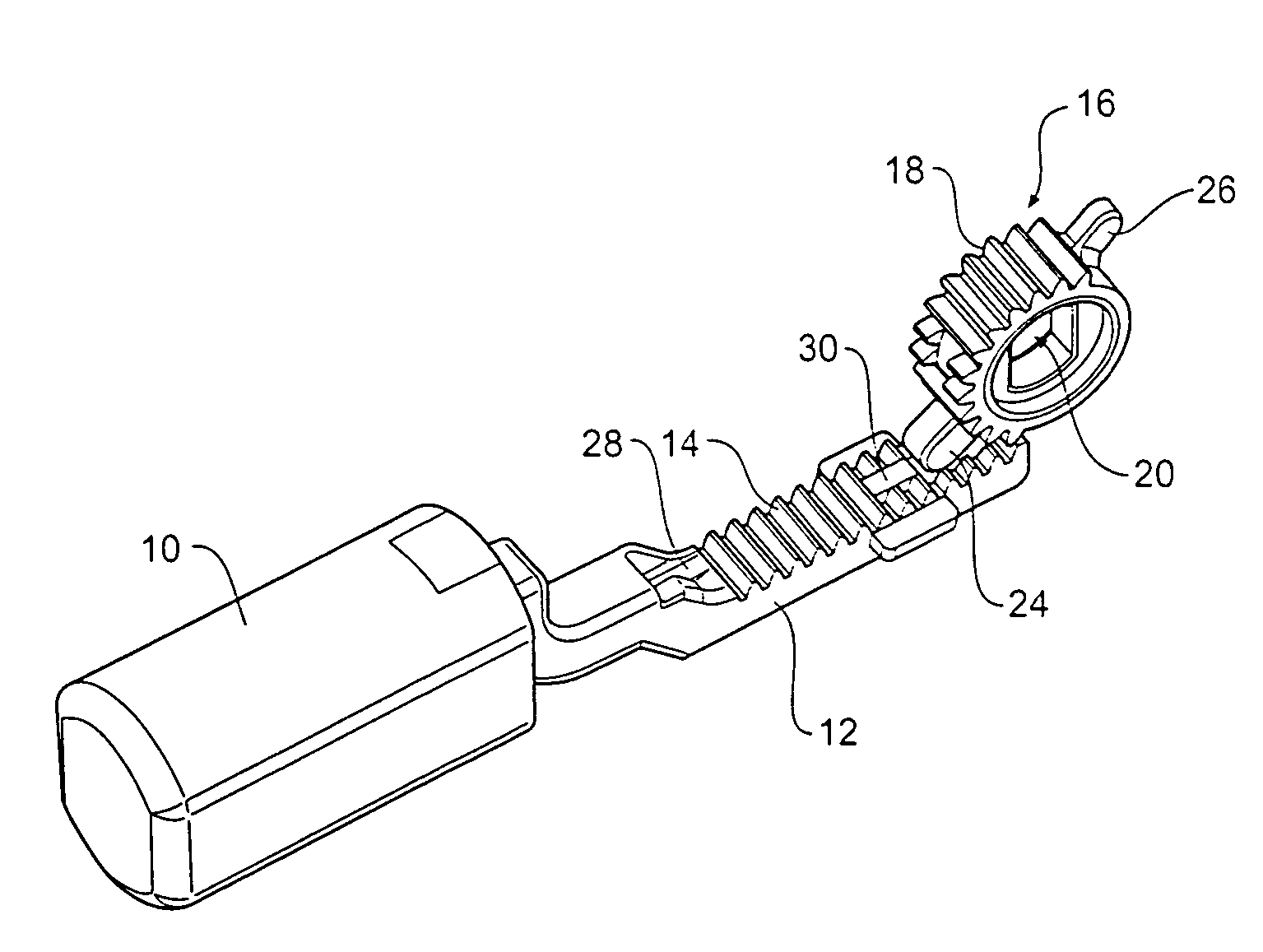
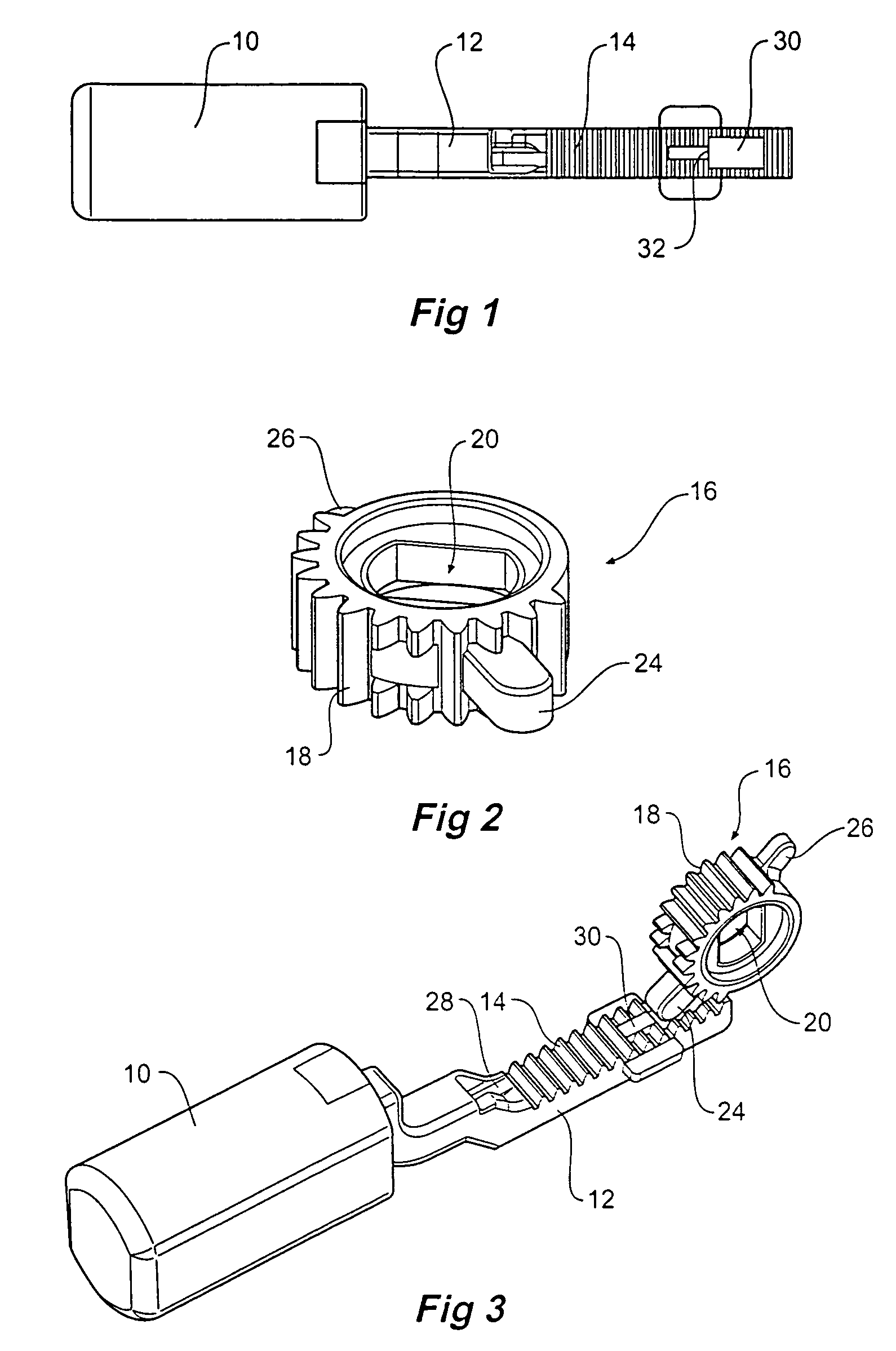
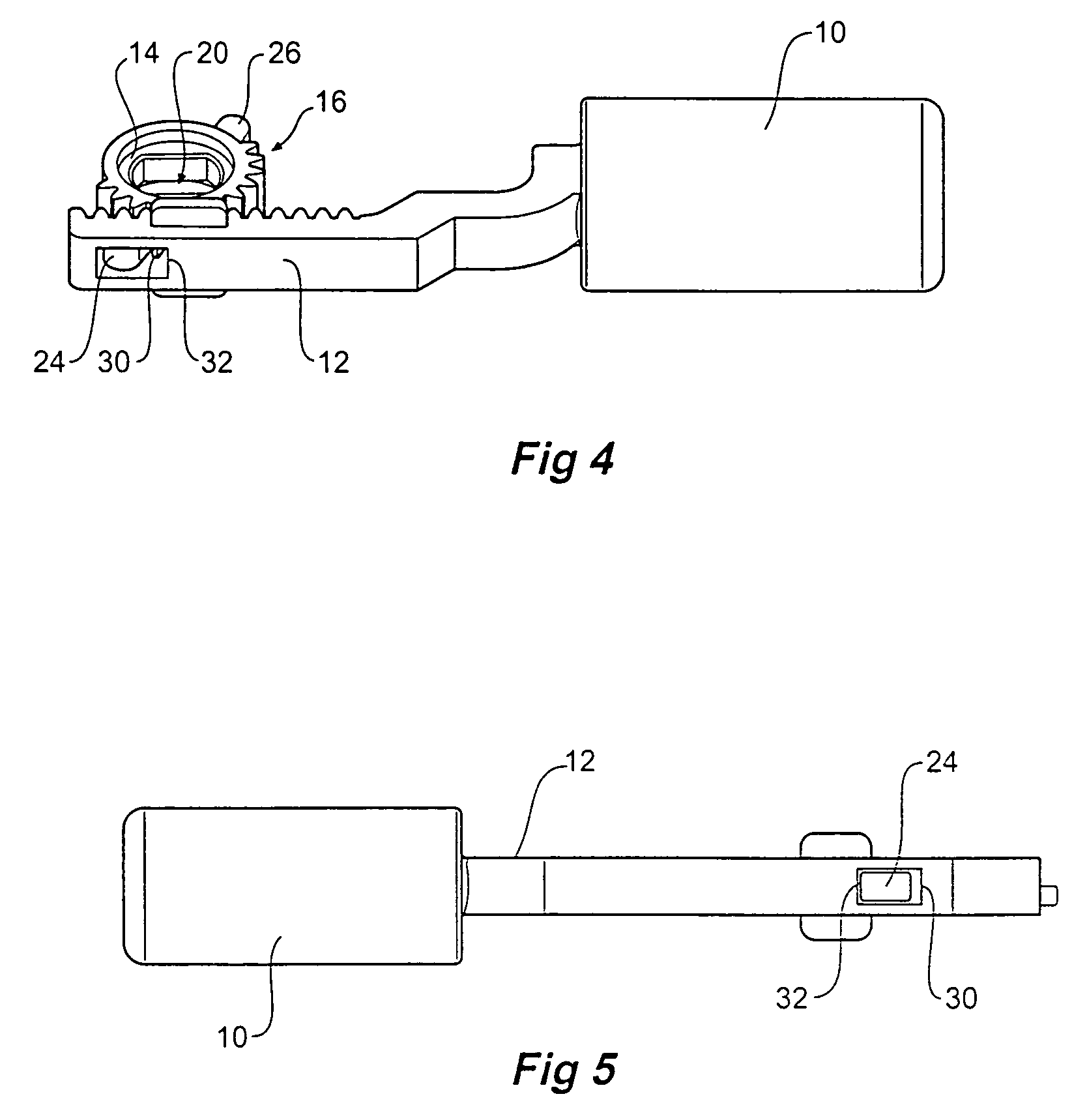
[0026]The following detailed description of the invention refers to the accompanying drawings. Although the description includes exemplary embodiments, other embodiments are possible, and changes may be made to the embodiments described without departing from the spirit and scope of the invention. Wherever possible, the same reference numbers will be used throughout the drawings and the following description to refer to the same and like parts.

[0027]The present invention is adapted for use in locks of the type where rotation of a driving shaft causes the bolt to move in and out of a doorframe. The rotational force is applied by either a key or by a driving motor. It is not intended to describe in detail the driving mechanism of such a lock or indeed other details of a complete lock assembly. For that the reader is referred to numerous patents that exist on this subject including an application by the present applicant titled Electronic deadbolt arrangement and allocated Internationa...


PUM


Abstract

A deadlocking assembly for use in locks that includes a rack supporting a bolt and a driving or pinion gear that drives the rack. Both the rack and the pinion gear have teeth that intermesh. The pinion gear further includes two arms, one of which acts as a stop when extending the bolt and the other that acts as a deadlock. When in the deadlocked position, forcing of the bolt is prevented by the other arm since the pinion gear teeth and the rack gear teeth at that position do not intermesh. A tab is further used to limit further rotation of the pinion gear.

Description

BACKGROUND OF THE INVENTION[0001]The present invention relates to lock and in particular to an improved deadlock arrangement where a bolt locks a door across an entrance.[0002]There are many locks that can be deadlocked. However, these locks are cumbersome and are not particularly adaptable for locks of the type that can be driven by two independent means, such as key and electric motor operation. Further they do not provide a good drive ratio requiring significant torque to operate the lock.[0003]It is an object of the present invention to propose a rack and pinion lock that overcomes at least some of the aforementioned problems or provides the public with a useful alternative.SUMMARY OF THE INVENTION[0004]Therefore in one form of the invention there is proposed a deadlocking assembly for use in locks said assembly including:[0005]a lock bolt operatively coupled to a rack;[0006]a drive means adapted to be rotatably driven and adapted to engage said rack to cause it to move in one a...

Claims


Application Information

Patent Timeline
Patent Type & Authority Patents(United States)
IPC IPC(8): E05C1/12E05B15/10E05B63/00E05C1/06
CPCE05B15/10E05C1/06E05B2063/207Y10T74/18976Y10T74/1967Y10T292/0843Y10T292/1021Y10T70/7102Y10T292/1018
Inventor KEIGHTLEY, KYM JOHN
Owner INOVEC
Why Eureka
Try Eureka