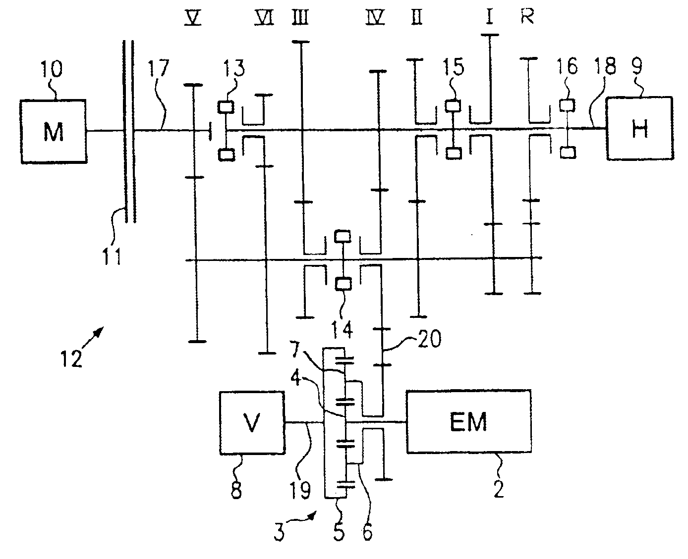
[0003]In contrast, the transfer case for distributing a driving force on a first axle and a second axle of a motor vehicle, according to the present invention, is very simply and compactly constructed and can be manufactured very cost-effectively. According to the present invention, the transfer case includes an epicyclic gear as well as an electrical machine. The epicyclic gear preferably is formed as a planetary gear and includes two central gears (for example, sun gear and internal gear) and a planetary support (bar) with at least one
planet. The electrical machine is connected with an element of the epicyclic gear, that is, with a planetary gear, for example, either with a sun gear, an internal gear, or a planetary gear support of the planetary gear. The transfer case is arranged between the first axle and the second axle of the motor vehicle. Therefore, a
coupling of the two axles of the motor vehicle takes place, as well as an electrical machine with the assistance of the epicyclic gear. According to the present invention, the degree of
coupling, that is, the force distribution on the two axles, of the transfer case between the first and the second axles is controlled by the electrical machine. In other words, the
power flux, which flows over the epicyclic gear, is controlled with the aid of the electrical machine. According to the present invention, therefore, a simple controlling of the distribution of force between the two driven axles is made possible. An essential
advantage of the transfer case of the present invention is that already, small electrical power for controlling the electrical machine suffices, in order to control a large
power flux between the two axles. Also, with a large installed output of the motor vehicle rotor, only low power in the electrical machine for controlling the power distribution is required.
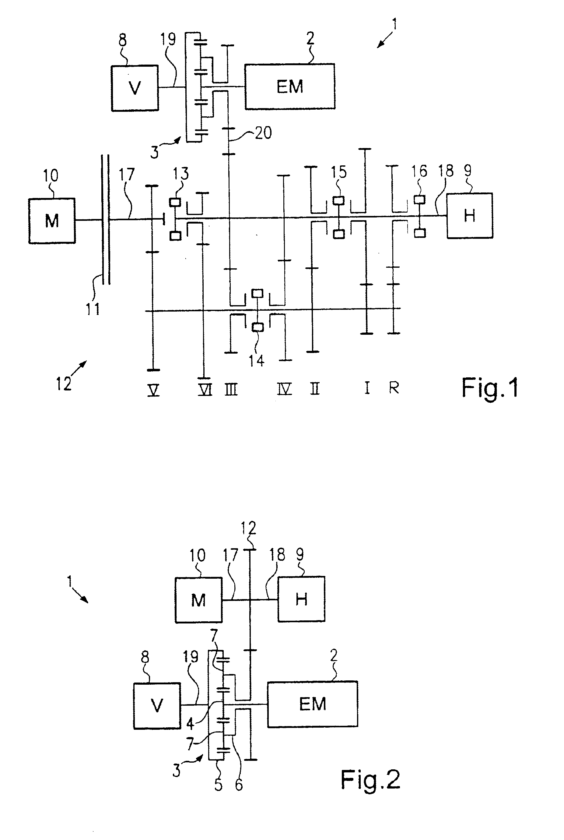
[0007]According to a further preferred embodiment of the present invention, the main elements of the planetary gear coupled with the front axle and the rear axle are connected with the axles such that they rotate with the same speed, based on the
coupling of the axles via wheel and road. The planetary gear revolves in this case as a block, so that mechanical roller losses in the gears can be avoided.
[0010]For increasing the stationary
gear ratio of the planetary gear, also another structure is possible. In particular, also two internal gears or two sun gears with a planetary support and step planets can be combined.
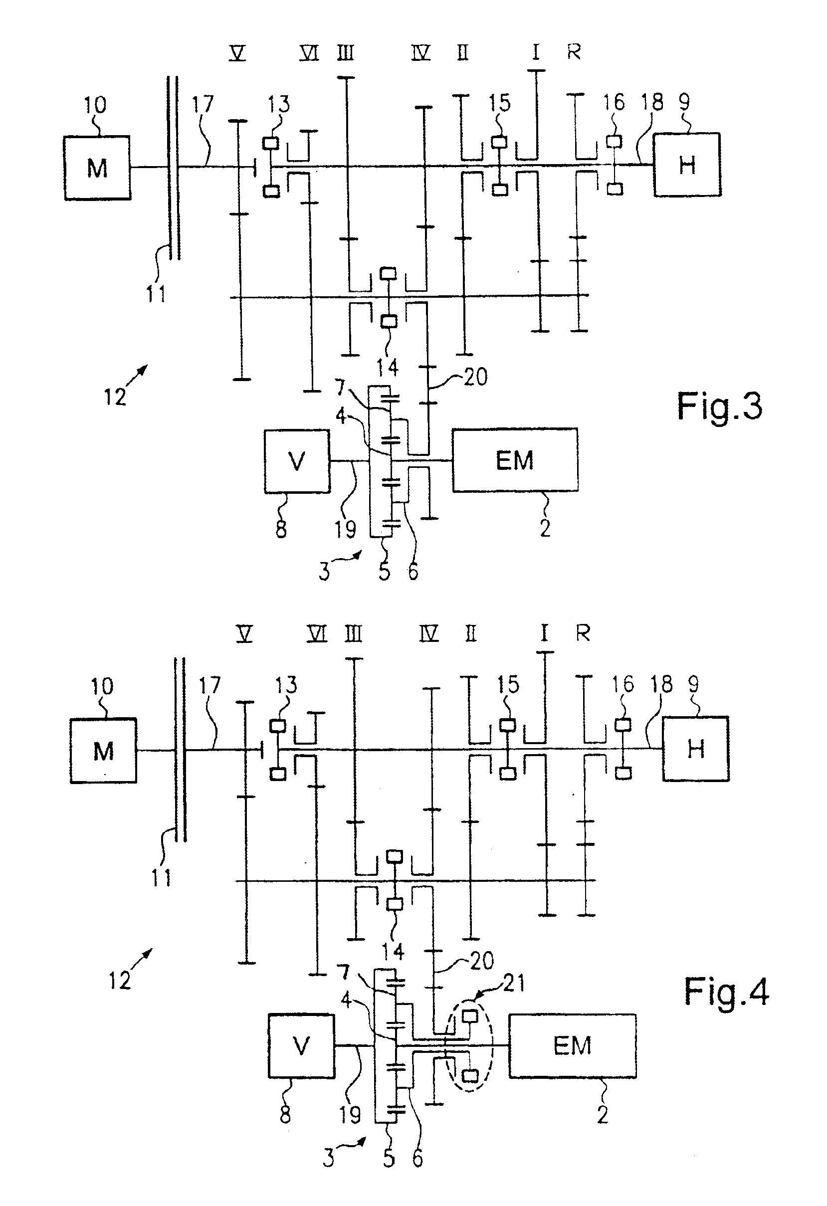
[0016]Since the transfer case is separated from the rear axle, no reactive effect on the rear axle takes place, which positively effects the vehicle stability. In addition the above-described arrangement can also be used for a boost-operation or for an electrical auxiliary drive of the vehicle. Since the electrical machine and the front axle are coupled fixedly in a switched state, the
power flux in this case can be controlled as desired. The output of the primary drive of the vehicle, therefore, is exclusively provided on the rear axle. In addition, with the above-described arrangement, also a mechanical reverse gear in the transmission of the vehicle can be omitted, since by means of the electrical machine, which exclusively drives the front axle, also electrical reverse can be driven.
[0019]Preferably, the electrical machine is operated as a generator of the motor vehicle, so that an
alternator that is conventional in motor vehicles can be eliminated. In addition, preferably, the electrical machine is used as a
recuperator for recovering braking energy. Further, the electrical machine is also used advantageously as an electrical motor vehicle drive, so that, for example, a
hybrid drive is possible, or the electrical machine for a boost-operation can be used, or the electrical machine can be used for an electrical reverse driving of the vehicle. The electrical machine can also be used for operating a compressor for an
air conditioning assembly in a motor vehicle. In addition, the electrical machine of the present invention can be operated, such that it can be used for an engine start of a
combustion engine of a motor vehicle, so that the
starter for
combustion engines that is common in motor vehicles can be eliminated.

