
Pivoting armest for enhancing side impact protection

a technology for side impact protection and armrests, which is applied in the direction of convertible stools, sofas, chairs, etc., can solve the problems of design and manufacture of armrests, and achieve the effect of reducing the likelihood and/or severity of injury, and sufficient strength and rigidity

Active Publication Date: 2007-03-27
FCA US
View PDF11 Cites 10 Cited by
  • Summary
  • Abstract
  • Description
  • Claims
  • Application Information

AI Technical Summary

Benefits of technology

The armrest assembly provides enhanced occupant protection by maintaining structural rigidity during everyday use while effectively deforming to reduce injury severity in side impacts, while also being cost-effective and comfortable.

Problems solved by technology

It is difficult, however, to design and manufacture an armrest that is structurally strong enough to withstand the type of loads to which it may be subjected during everyday use and that is also capable of deforming so as to reduce injury in a crash.

Method used


Image

  • Pivoting armest for enhancing side impact protection
  • Pivoting armest for enhancing side impact protection
  • Pivoting armest for enhancing side impact protection

Examples


Embodiment Construction

[0014]The following description of the preferred embodiment(s) is merely exemplary in nature and is in no way intended to limit the invention, its application, or uses.

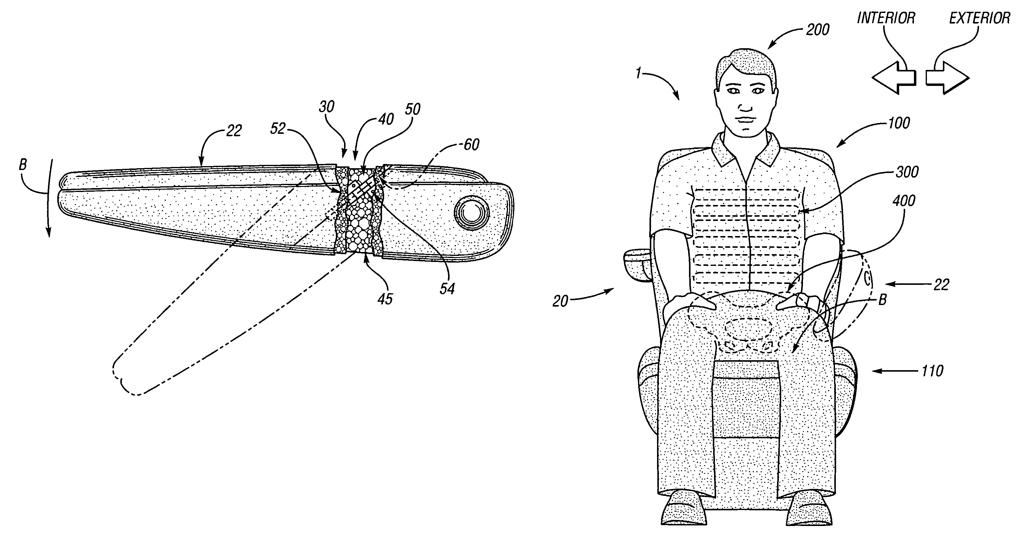
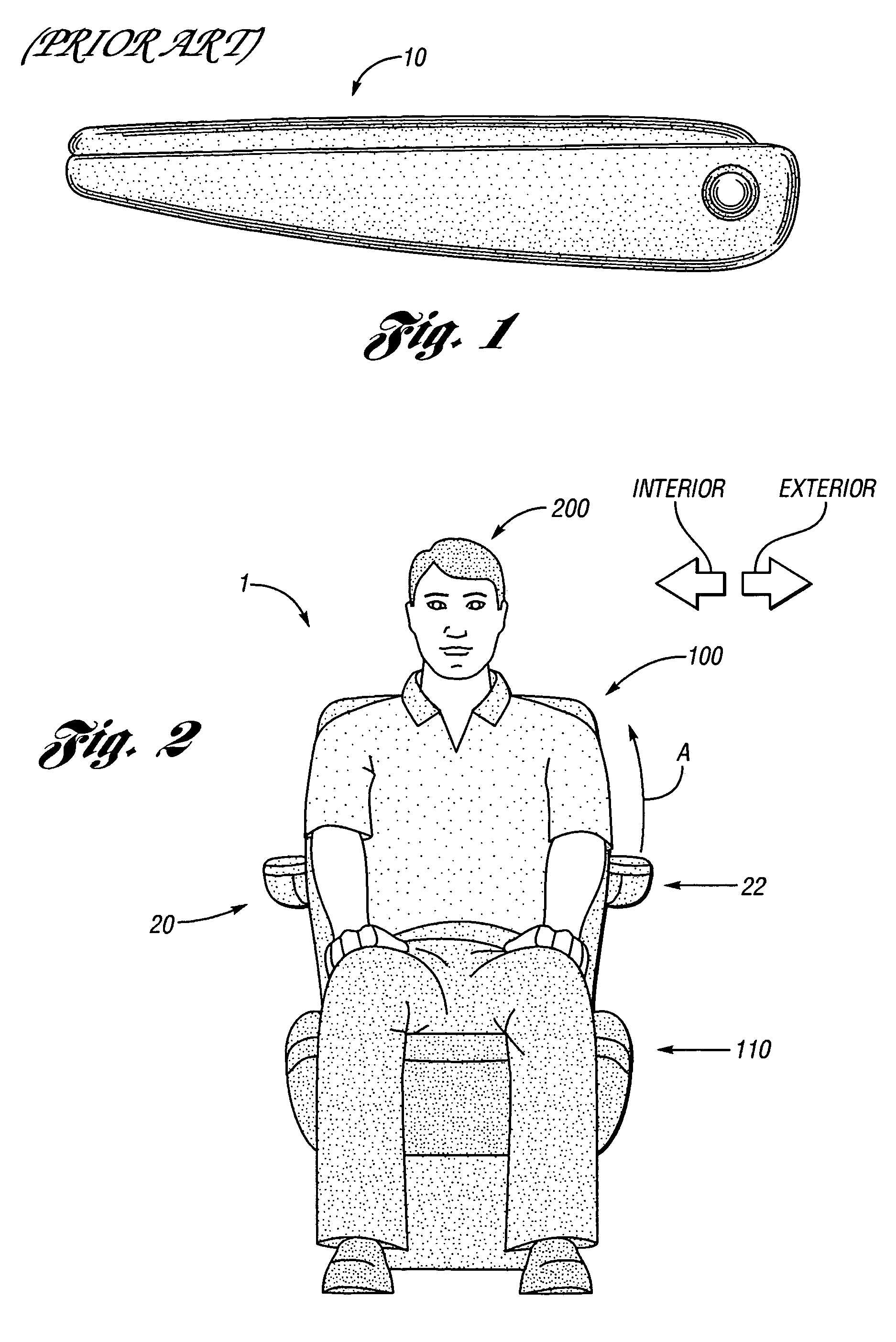
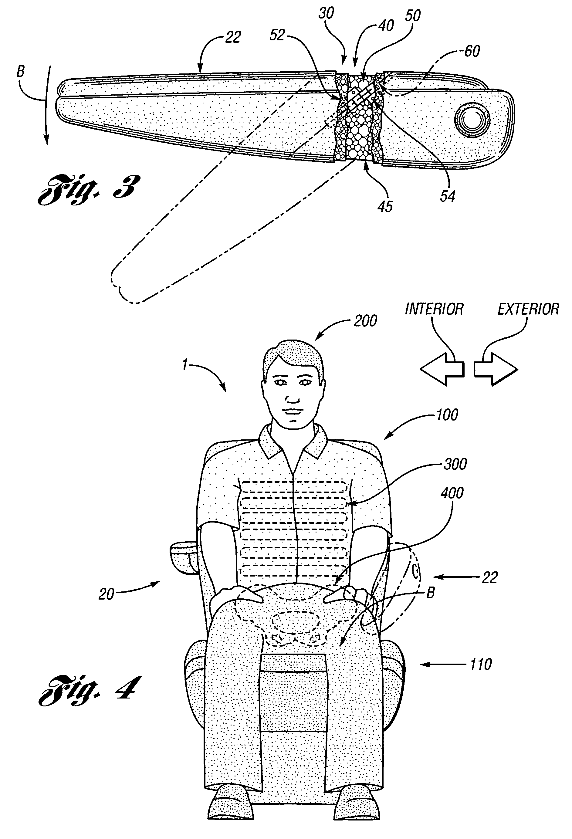
[0015]Turning now to the drawings, FIG. 2 shows a passenger 200 in a sitting position in a seat assembly 1. The seat assembly includes a seat 110 attached to a seat back 100. The seat assembly 1 further includes armrests 20, 22 which are each attached to a pin (not shown). The pin is pivotally attached to the seat back 100 such that the armrests 20, 22 may be rotated in the direction of arrow A, in an arc relative to the seat back 100 between a raised, stored position aligned in the substantially vertical plane of the seat back 100 and a lowered, use position aligned substantially perpendicular to the seat 110. The seat assembly 1 may be of conventional design wherein the seat back 100 is pivotally coupled to the seat 110 to permit the seat back 100 to be folded down on top of the seat 110.

[0016]FIG. 3 shows an armres...


PUM


Abstract

An armrest assembly for a motor vehicle seat having a first support member pivotably mounted to a seat structure, a second support member rotatably mounted to the first support member, and a biasing arrangement positioned relative to the first and second support members. The biasing arrangement exerts a predetermined biasing force on the second support member to prevent the second support member from rotating relative to the first member until a sufficient load force is applied to the armrest to overcome the biasing threshold.

Description

FIELD OF THE INVENTION[0001]The present invention relates to an armrest assembly for a motor vehicle seat, and specifically to an armrest assembly for a motor vehicle seat adapted for improved occupant protection during a side impact.BACKGROUND OF THE INVENTION[0002]Automotive vehicle seat assemblies typically have a seat, a seat back and an armrest attached to the seat back to provide a surface on which the vehicle occupant may rest their elbow or forearm. Known armrests, such as the armrest 10 shown as prior art in FIG. 1, are typically connected to a pin which is in turn pivotably attached to the seat back such that the armrest can rotate in an arc with respect to the seat back between a raised, stored position and a lowered, use position. As a result, armrests must possess sufficient rigidity and strength to withstand the loads applied during everyday use of the vehicle.[0003]In recent years, many efforts have been made reduce potential injury to vehicle occupants during a side ...

Claims


Application Information

Patent Timeline
Patent Type & Authority Patents(United States)
IPC IPC(8): B60N2/46B60N2/75
CPCB60N2/4633B60N2/767
Inventor CROSSMAN, MARK WRAJAGOPALAN, RAJKUMARVARADAPPA, SHARATH
Owner FCA US
Learn More