
Sparker for flash lamp

Active Publication Date: 2016-06-21
EXCELITAS TECH
View PDF1 Cites 0 Cited by
  • Summary
  • Abstract
  • Description
  • Claims
  • Application Information

AI Technical Summary

Benefits of technology

The patent text describes a flash lamp assembly with a compact, low-cost, and simple design that includes a sparker for reliability. The sparker lowers the work function of the electrodes in the flash lamp, reducing flash-to-flash variation. The sparker is integrated directly into the flash lamp, eliminating the need for separate sub-assemblies and reducing labor and cost associated with flash lamps and flashers. By placing the sparker in a flat ground plane away from the main lamp discharge, the electrical inductance is reduced, improving discharge timing and energy. Overall, the patent text provides a technical solution for improving the performance and reliability of flash lamp assemblies while saving costs.

Problems solved by technology

Some flash lamp designs can be structurally complex and difficult and costly to manufacture.

Method used


Image

  • Sparker for flash lamp
  • Sparker for flash lamp
  • Sparker for flash lamp

Examples


Embodiment Construction

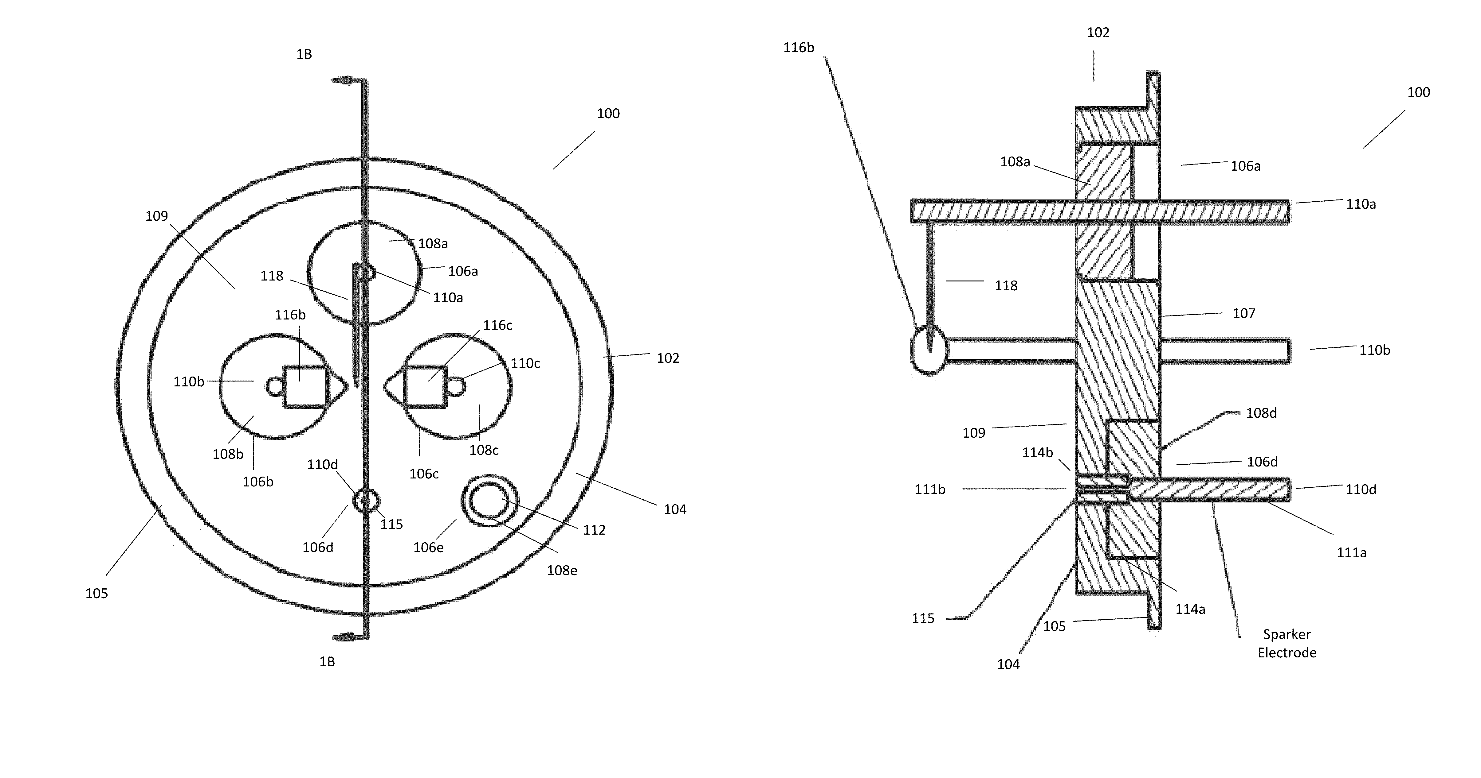
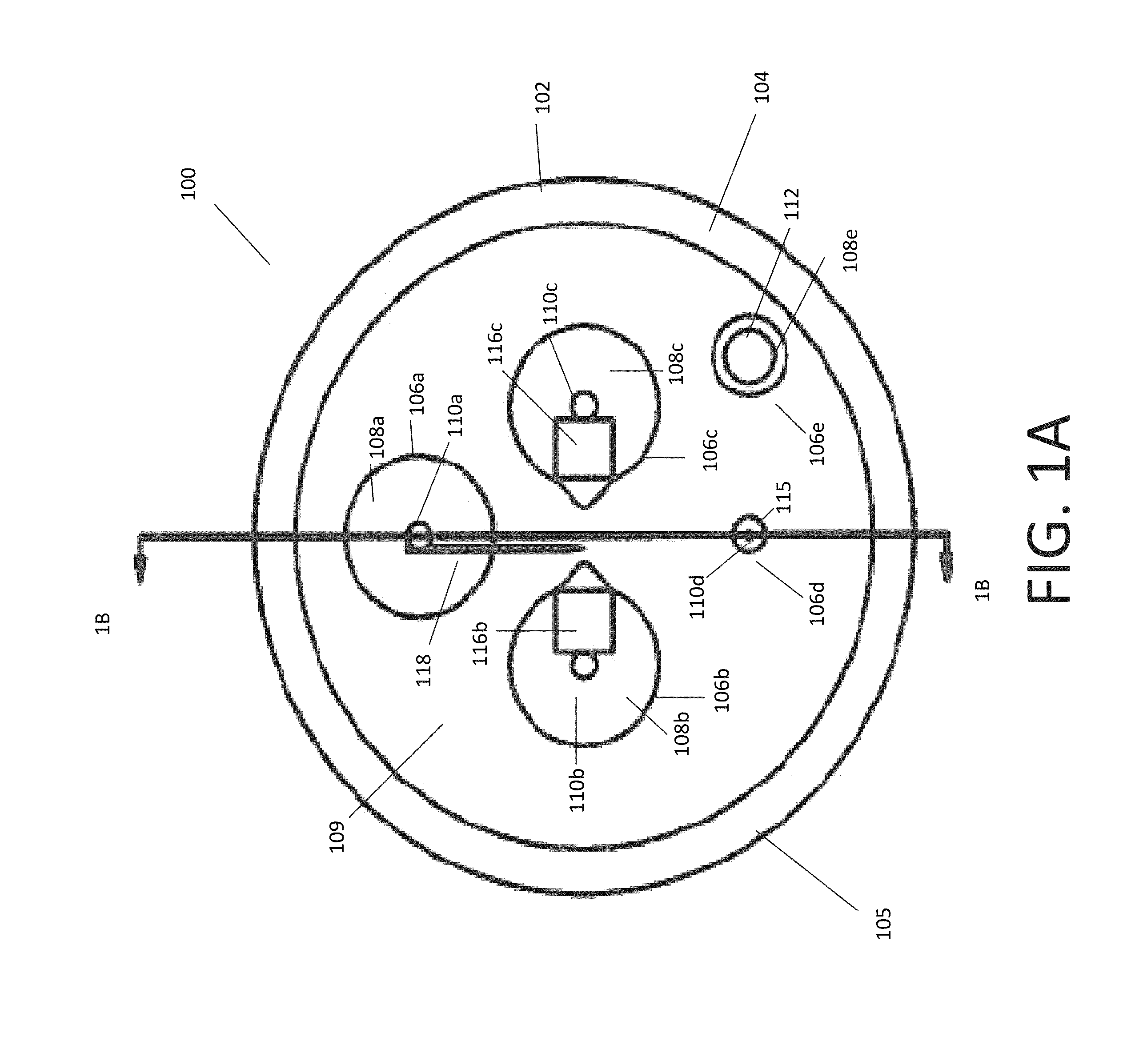
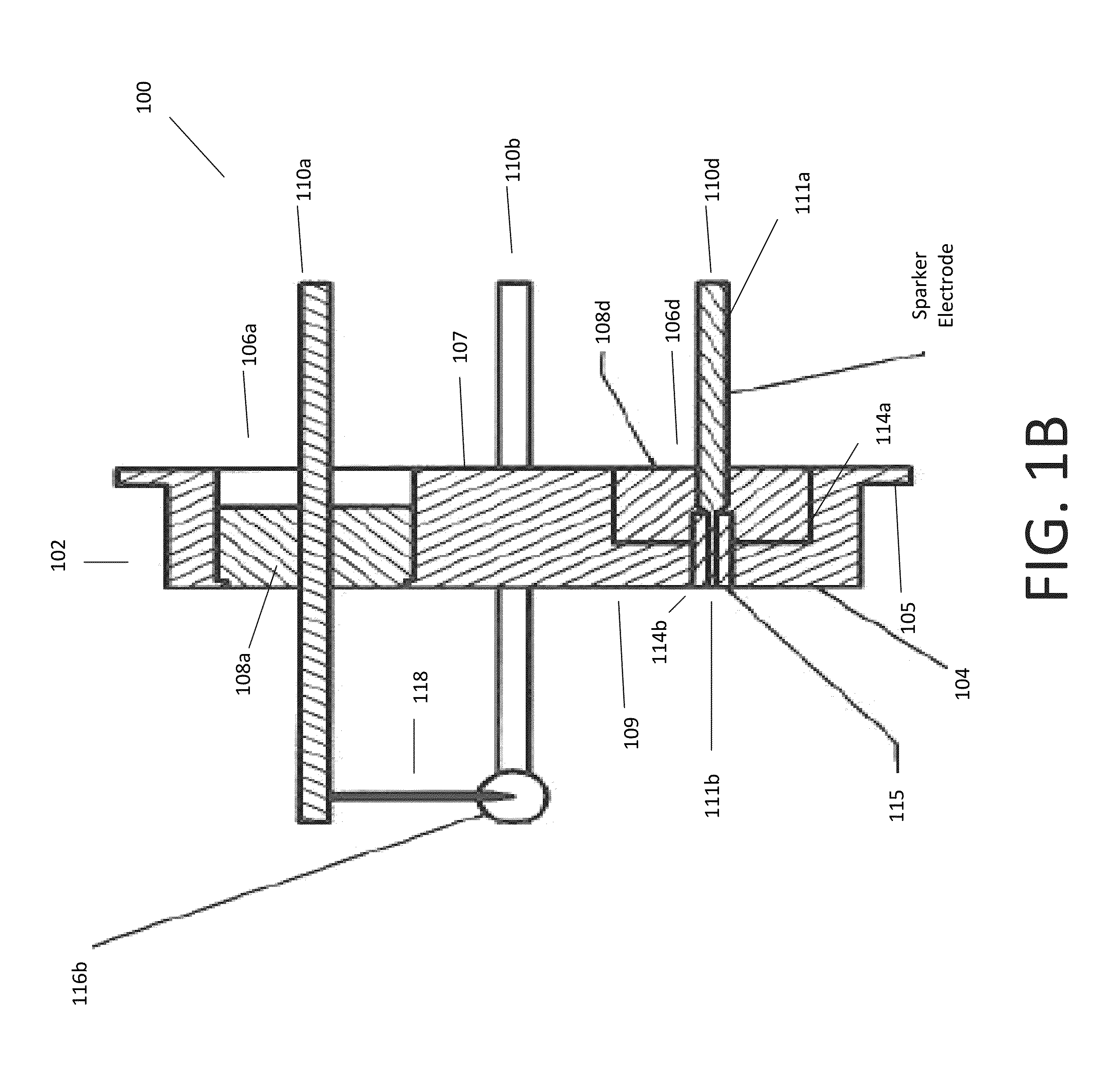
[0024]FIG. 1A is a top view of an exemplary flash lamp 100 with its cover removed. FIG. 1B is a cross-sectional side view of the flash lamp 100 taken along the line labeled 1B-1B in FIG. 1A. The flash lamp 100 represented in FIG. 1A and FIG. 1B is an electric arc lamp configured to produce extremely intense, incoherent, full-spectrum white light for very short durations. In a typical implementation, the flash lamp 100 in FIG. 1A and FIG. 1B has certain structural aspects that are beneficial in their own right and also lead to simpler flash lamp manufacturing processes.

[0025]The illustrated flash lamp 100 has a flash chamber, which is not specifically identified in FIG. 1A or 1B, but that would be an enclosed space defined by the base assembly 102 and a cover, which is not shown in FIG. 1A or 1B. In FIG. 1A, the flash chamber would be configured so that it extended out of the page and, in FIG. 1B, the flash chamber would be configured so that it extended to the left of the illustrate...


PUM


Abstract

A base assembly for a flash lamp is disclosed. The base assembly has an integrated sparker and includes an electrically conductive header having a surface that defines a boundary of a flash chamber for the flash lamp. There is an opening in the surface of the electrically conductive header and an electrically conductive lead within the opening. The electrically conductive lead is electrically insulated from surrounding portions of the electrically conductive header. A distal end of the electrically conductive lead is substantially flush with the surface of the electrically conductive header.

Description

FIELD OF THE INVENTION[0001]This disclosure relates to a sparker for a flash lamp and, more particularly relates to a sparker integrated into a hermetic feed-through assembly for the flash chamber in the flash lamp.BACKGROUND[0002]Flash lamps tend to be the light engine of choice for high performance flash and arc lamp applications such as medical and industrial spectroscopy, laser pumping, digital and studio photography, warning beacons and strobes, stroboscopic and effect lighting. Generally speaking, Xenon and Krypton flash lamps are confined arc flash lamps which typically produce microsecond to millisecond duration pulses of broadband light of high radiant intensities. Capable of operating at high repetition rates, these flash lamps typically can generate light over a continuous spectrum from ultraviolet to infrared.[0003]Some flash lamp designs can be structurally complex and difficult and costly to manufacture. Improvements are needed.SUMMARY OF THE INVENTION[0004]In one aspe...

Claims


Application Information

Patent Timeline
IPC IPC(8): H01J17/18H01J61/90H01J61/16
CPCH01J61/90H01J61/16H01J9/30H01J9/34H01J61/363H01J61/366
Inventor VIDAL, DAVID
Owner EXCELITAS TECH
Learn More