Method for manufacturing a hollow blade for a stator or rotor component

Inactive Publication Date: 2005-03-03
VOLVO AERO CORP
View PDF5 Cites 10 Cited by
  • Summary
  • Abstract
  • Description
  • Claims
  • Application Information

AI Technical Summary

Benefits of technology

[0012] One object of the present invention is to provide a method for connecting a support element to a blade wall tha

Problems solved by technology

One disadvantage of this method is that it is relatively time-consuming to place the stay in the intended position and to remove it after welding has been carried out.
It is also difficult to achieve sufficiently good quality.
In structural terms, it is not an optimum solution, because stress concentrations tend to occur, resulting i

Method used


Image

  • Method for manufacturing a hollow blade for a stator or rotor component
  • Method for manufacturing a hollow blade for a stator or rotor component
  • Method for manufacturing a hollow blade for a stator or rotor component

Examples


Example

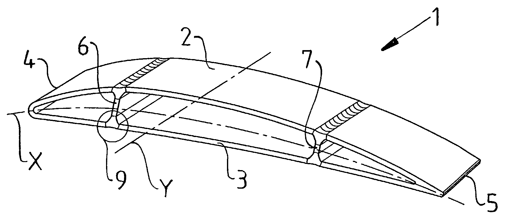
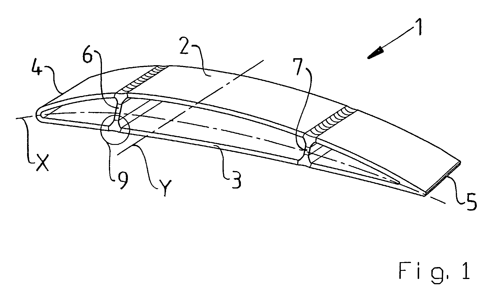
[0021]FIG. 1 shows a hollow blade 1 in a perspective view. The blade 1 has a first side wall 2 and a second side wall 3 located opposite one another. The first side wall 2 has a convex cross-sectional shape, and the second side wall 3 has a concave cross-sectional shape. A mean camber line, X, is indicated by a dot-dash line. The mean camber line extends centrally in the blade from a front end 4 of the blade to a rear end 5 of the blade. The front end and rear end are described in relation to the direction from which the gas flow is intended to act during use of the blade in a stator or rotor component.

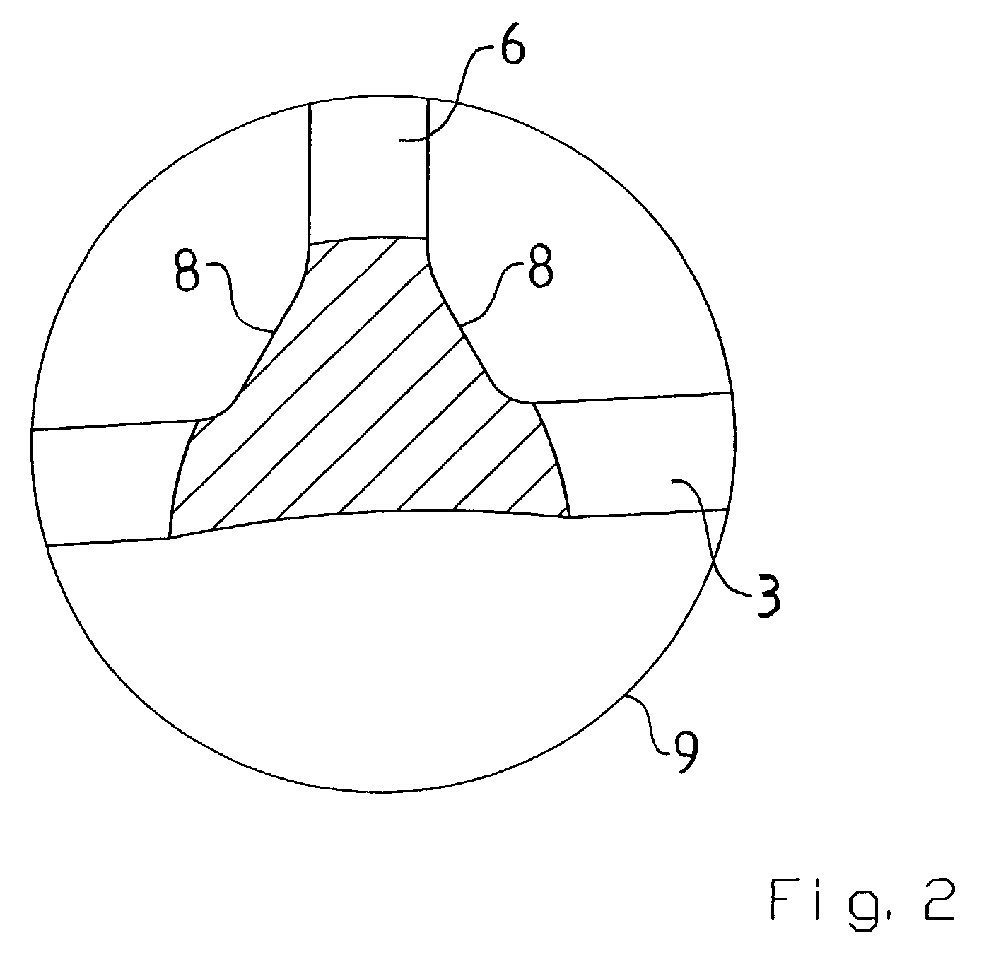
[0022] Furthermore, two plate-shaped support elements 6, 7 are arranged inside the blade 1. The plate-shaped support elements 6, 7 are arranged upright inside the blade 1 and extend essentially at right angles to the mean camber line, X. Each of the plate-shaped support elements 6, 7 is elongate and extends in the transverse direction of the blade 1, indicated here by a broken line, ...


PUM

PropertyMeasurementUnit
Angleaaaaaaaaaa
Shapeaaaaaaaaaa

Abstract

Method for manufacturing a hollow blade configured to function as a stator or rotor component and having at least one support element positioned between two opposite blade walls, and joined together by welding. The support element is joined together with at least one of the blade walls by means of laser-welding from the outside of the blade in such a way that the joined-together portions of the support element and the blade wall form a T-shaped joint.

Description

CROSS REFERENCE TO RELATED APPLICATIONS [0001] The present application is a continuation patent application of International Application No. PCT / SE02 / 01457 filed 14 Aug. 2002 which was published in English pursuant to Article 21(2) of the Patent Cooperation Treaty, and which claims priority to Swedish Application No. 0102882-8 filed 29 Aug. 2001. Both applications are expressly incorporated herein by reference in their entireties.BACKGROUND OF INVENTION [0002] 1. Field of the Invention [0003] The present invention relates to a method for manufacturing a hollow blade intended for a stator component or rotor component and having at least one support element positioned between two opposite blade walls, and joined together therewith. The stator or rotor component can be used, for example, in a gas turbine, and in particular in a jet engine. [0004] The term jet engine includes various types of engines which take in air at relatively low speed, heat it by combustion, and discharge it at m...

Claims


Application Information

Patent Timeline
IPC IPC(8): B64C3/18B23K26/20B23K26/24B23P15/04F01D5/14F01D5/18F01D9/02F02C7/00
CPCB23K26/24B23K2201/001B23P15/04Y10T29/49339Y10T29/49336Y10T29/49325F01D5/147B23K2101/001
Inventor LUNDGREN, JANCARLSSON, JOAKIMJONSSON, PETERNORDIN, BORJE
Owner VOLVO AERO CORP
Why Eureka
Try Eureka