Sound suppression apparatus

a technology of sound suppression and apparatus, which is applied in the direction of sound producing devices, fuel intake silencers, domestic heating details, etc., can solve the problems of large quantities of undesirable noise, large amounts of undesirable noise, and large amounts of undesirable noise, and achieve high levels of targeted low-frequency control, good broadband performance, and high efficiency

Active Publication Date: 2017-08-03
AAF LTD
View PDF2 Cites 10 Cited by
  • Summary
  • Abstract
  • Description
  • Claims
  • Application Information

AI Technical Summary

Benefits of technology

[0022]By providing such a hybrid sound suppression apparatus, both resistive and reactive sound-attenuating elements are able to interact with a gas stream passing the outer surface of the apparatus and a sound suppression performance which exceeds the individual contributions expected from resistive or reactive elements alone can thereby be obtained. Further, by providing such an apparatus, the resistive and reactive elements interact with the gas stream via a common external surface of the apparatus, the aerodynamic properties of the apparatus as a whole can be selected so as to provide enhanced sound suppression performance while minimising unwanted disruption to a passing gas stream.
[0047]Embodiments of the present invention may provide a sound suppression apparatus which is able to suppress a broad range of unwanted frequencies, for example high levels of targeted low-frequency control as well as good broadband performance, at high efficiency and which is cost-effective to manufacture and install.

Problems solved by technology

Firstly, the processes which use or generate the gas, such as combustion processes, may generate large quantities of undesirable noise.
Further, where the rate of transport of gas is to be high, the transport of gas can be associated with the generation of undesirable noise.
Also, the means by which the gas is drawn into or drawn out of the location where the gas is produced or consumed, for example fans and the like, can generate substantial amounts of undesirable noise themselves.
Transport of this noise via the gas in the duct to the surrounding environment is undesirable.
Often, the materials used as resistive sound-absorbing materials, such as rock wool or glass wool, are relatively fragile and can be eroded by the passage of high velocity gas, especially passing at elevated temperatures.
For frequencies below this limit, the sound-absorption process is far less efficient.
Increasing the internal cross-sectional area of the duct to counter this effect reduces the sound absorption performance.
However, such an approach results in larger, heavier and correspondingly more expensive gas handling equipment.
Although reactive sound-attenuating elements can be effective at suppressing a well-defined frequency and its harmonics, reactive sound-attenuating elements lack the broad-band sound-absorbing properties of the resistive absorber.
Furthermore, providing such sound-attenuating elements in the walls of a duct again entails increasing the duct dimensions for a given desired gas flow rate and requires costly engineering of the walls of the duct to provide the desired resonant sound-absorbers at appropriate locations in the duct.
Finally, providing such sound-attenuating elements in the walls of a duct is ineffective in suppressing higher frequencies which propagate in the duct at higher-order modes of the duct, since the acoustic energy associated with such frequencies propagates along the duct in mode patterns which are distant from, and thus interact less, with the walls of the duct.
While such an approach can achieve broadband sound suppression with the resistive absorber and sound-absorption at specific frequencies with the resonant absorbing sections, such a configuration requires an increase in the external cross-sectional area of the duct for a given internal cross-sectional area, and thus inevitably results in a requirement for large, heavy and expensive ducting.
Furthermore, since the frequency spectrum associated with a gas transport duct results from a combination of the rate at which gas is transported along the duct, the gas-producing or gas-consuming equipment which is connected to the duct, the presence of intermediate gas treatment units such as filters, and the length and geometry of the duct itself, the provision of reactive and resistive sound-absorbers as part of the duct requires complex and expensive custom engineering work in designing the duct to meet the specific requirements of the project.

Method used


Image

  • Sound suppression apparatus
  • Sound suppression apparatus
  • Sound suppression apparatus

Examples


first embodiment

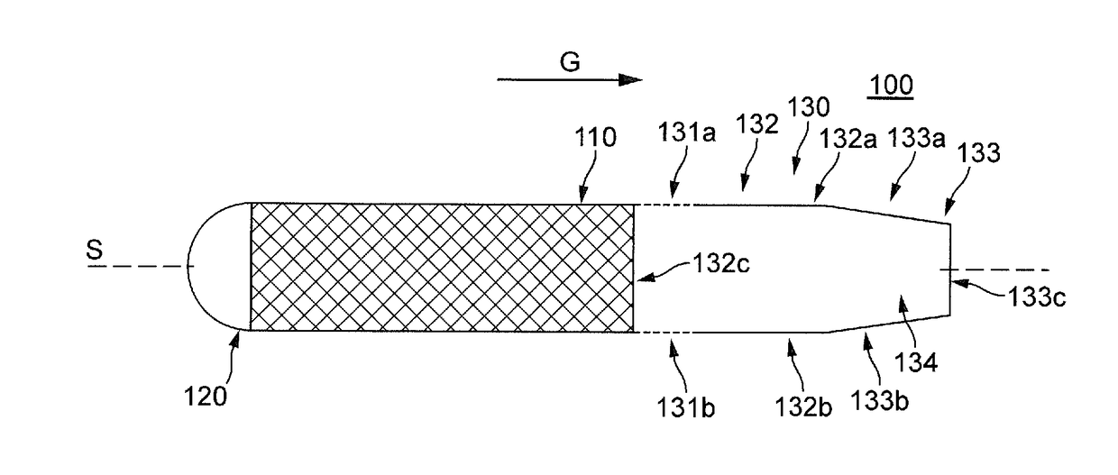
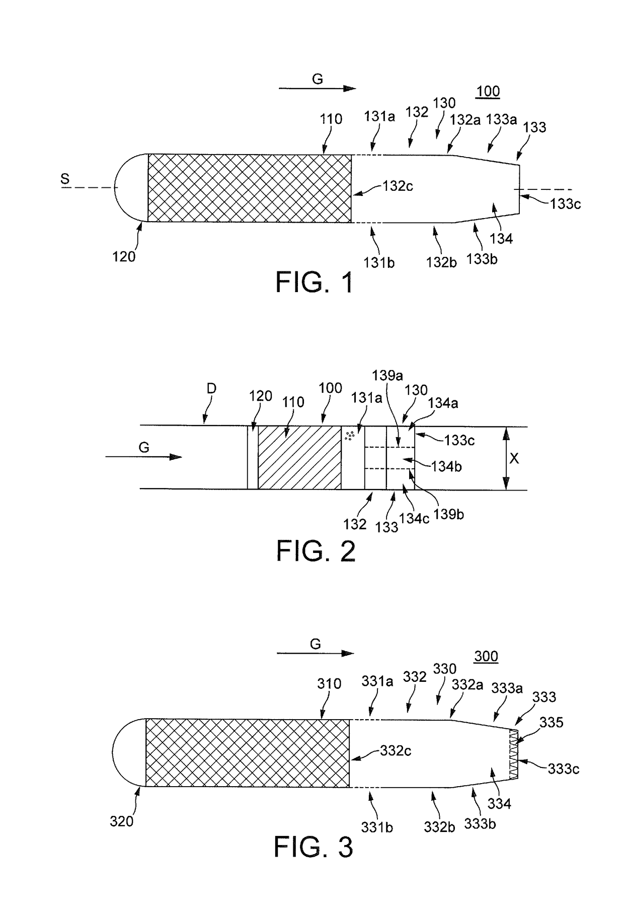
[0075]According to the present invention, there is provided a sound suppression apparatus as shown in FIG. 1.

[0076]FIG. 1 shows a sound suppression apparatus 100 having a configuration similar to the baffle 2500 of FIG. 25. Where the configuration is the same or similar, no further detail will be given, and the reader is referred to the corresponding elements of the baffle 2500 of FIG. 25.

[0077]The sound suppression apparatus 100 has a mass of resistive sound-absorbing material 110 arranged between a cap portion 120 in an upstream direction of gas flow G and a housing 130 arranged in a downstream direction of gas flow G, in a similar manner as baffle 2500 shown in FIG. 25.

[0078]As for baffle 2500 in FIG. 25, in the cross-section shown in FIG. 1, the resistive sound-absorbing material has straight, generally parallel sides, to permit the gas to flow smoothly and aerodynamically past. Aerodynamic flow, as herein discussed, refers to substantially laminar flow in a direction of elongat...

eighth embodiment

[0118]In some configurations, the further void provided between partition 1333e and trailing end wall 1333c can be used to provide a further reactive sound-attenuating element of the type shown in any of the preceding embodiments. Such a configuration having a further resonator can, in a similar manner to the eighth embodiment shown in FIG. 9, allow two frequencies to be addressed by two appropriately-tuned cavity resonators.

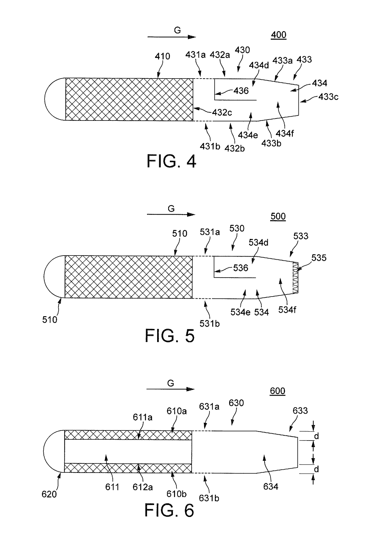
[0119]FIG. 14 shows a thirteenth embodiment of the present invention, having a further modified resonator configuration within housing 1430. The configuration of FIG. 14 provides two L-shaped partition members 1434a, 1434b, one extending inwardly from wall 1432a and then extending rearwardly towards trailing end wall 1433c, the other extending inwardly from tapered wall 1433b towards tapered wall 1433a and then extending forwardly towards end wall 1432v. The effect of providing two partition members as shown in FIG. 14 is to lengthen the resonant path in resonan...


PUM


Abstract

A sound suppression apparatus for installation inside a gas transport duct is provided. The sound suppression apparatus comprises a resistive sound-absorbing element (110) and a housing providing a reactive sound-attenuating element (130) communicating with a surrounding of the apparatus via opening in an outer surface of the housing. An outer surface of the sound suppression apparatus comprises an outer surface of the resistive sound-absorbing element and the outer surface of the housing. A gas transport duct comprising the sound suppression apparatus is also provided.

Description

FIELD OF THE INVENTION[0001]The present invention relates to a sound suppression apparatus, and particularly to a sound suppression apparatus suitable for installation inside a gas transport duct. The present invention also provides gas transport ducts having sound suppression apparatuses in accordance with the invention arranged therein, and may be especially suitable for installation in intake or exhaust ducts of power generation equipment or in the oil and gas industries.BACKGROUND[0002]Many industrial processes require the intake or exhaust of large quantities of gas. Such industrial processes include power generation, heating, ventilation, and air conditioning (HVAC), forced-air cooling and fume extraction, as well as in processes, especially combustion processes, of the oil and gas industries.[0003]Transport of such gas is usually achieved by flowing the gas through ducting of appropriate dimension and construction from the source of the gas to a location at where it is requir...

Claims


Application Information

Patent Timeline
Patent Type & Authority Applications(United States)
IPC IPC(8): F16L55/033F01N1/08F24F13/24F02M35/12
CPCF16L55/033F24F13/24F01N1/08F02M35/12F02M35/1216F01N1/085F16L55/0331G10K11/161G10K11/172G10K11/175F24F2013/242F24F2013/245F16L55/0336F01N1/02F01N1/04F01N1/10F01N1/24F01N2240/20F01N2490/20F02M35/1255F02M35/1272F01N2210/00
Inventor HILL, JAMES MATTHEWMALECKI, COLIN ALEXANDERWILLIAMS, PAUL TIMOTHYABOM, MATSKIRBY, RAYMOND
Owner AAF LTD
Why Eureka
Try Eureka