Force Limiting Device for a Motor Vehicle

a technology of force limiting device and motor vehicle, which is applied in the direction of bumpers, transportation and packaging, gearing, etc., can solve the problems of limited energy acting on the passenger compartment and limited energy acting on the occupants during their forward displacement, and achieve the effect of good chance of relative rotation braking

a technology of force limiting device and motor vehicle, which is applied in the direction of bumpers, transportation and packaging, gearing, etc., can solve the problems of limited energy acting on the passenger compartment and limited energy acting on the occupants during their forward displacement, and achieve the effect of good chance of relative rotation braking

US20110172054A1Active Publication Date: 2011-07-14AUTOLIV DEV AB

Image

  • Force Limiting Device for a Motor Vehicle
  • Force Limiting Device for a Motor Vehicle
  • Force Limiting Device for a Motor Vehicle

Examples


Embodiment Construction

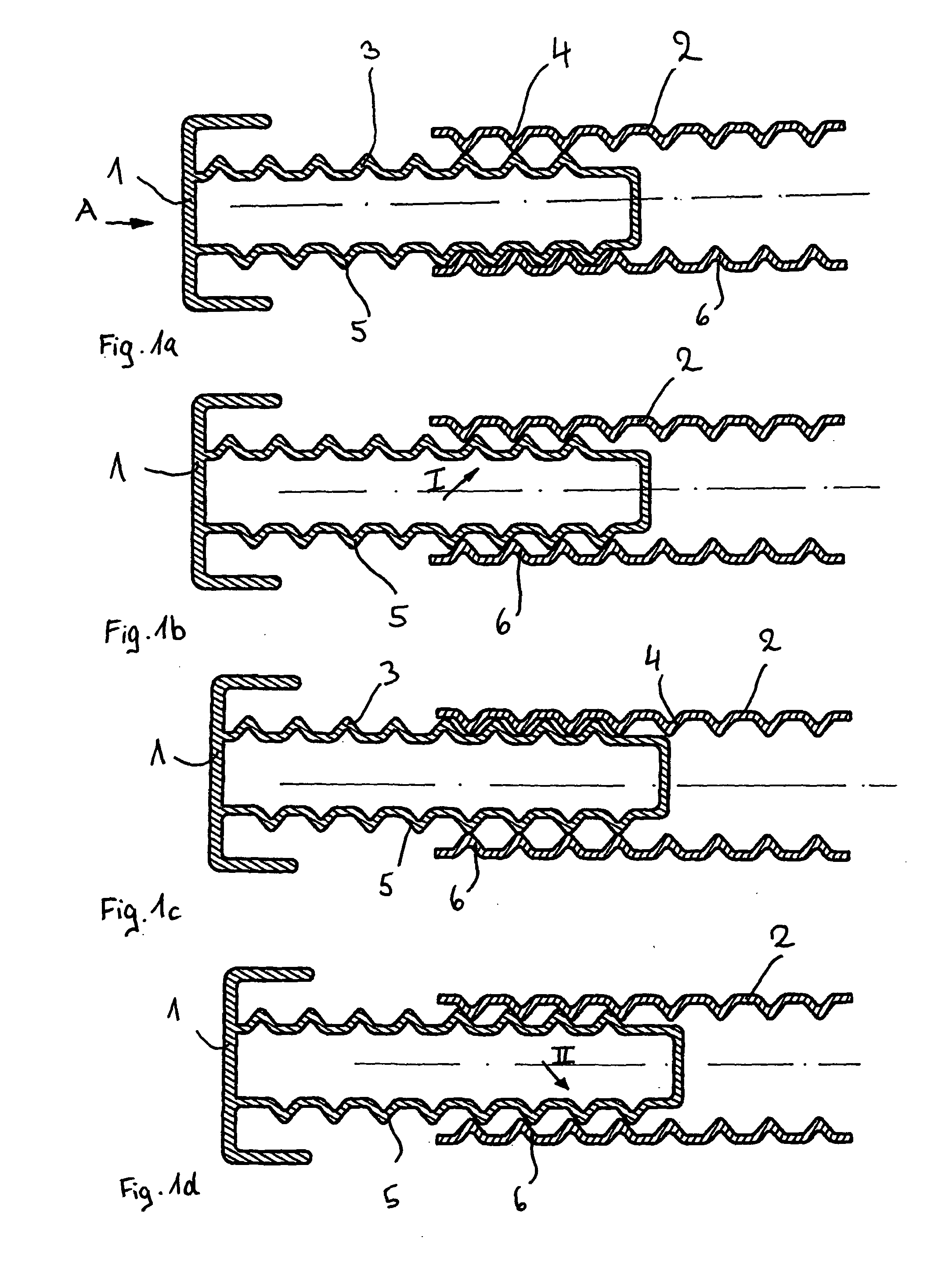
[0035]In the FIGS. 1a to 1d, firstly, an exemplary embodiment of the invention can be seen in which the two parts 1 and 2 are provided which form a load limiting mechanism according to the invention and can be provided in different applications in the motor vehicle. One of the parts 1 or 2 is arranged in a fixed manner to the vehicle, in this case, part 2, while the respective other part 1 or 2, here part 1, undergoes a load limited movement. The part 1 can be, for example, a steering wheel or a part coupled to it, or a deformation member in the vehicle structure. The load limiting mechanism is suitable for many applications in motor vehicles in which energy is intended to be dissipated (by reducing the magnitude of acceleration). Accordingly, a load limited deformation or movement for the protection of the vehicle occupant or the passenger compartment is provided.

[0036]The part 1 is provided with gears 3 and 5 on its opposite sides and engages in a part 2 which is also provided wit...


PUM


Abstract

A load limiting mechanism for a motor vehicle, comprising at least two parts (1, 2, 10, 12, 16, 20, 21, 46, 22, 40) controlled relative to one another with a frequency controlled oscillating movement. The parts (1, 2, 10, 12, 16, 20, 21, 46, 22, 40) moving relative to one another comprise interlocking gears (3, 4, 13, 15, 24, 25, 26, 27) and the frequency controlled oscillating movement results thereby that at least one of the parts (1, 10, 21, 22) compared to the other part (2, 12, 16, 20, 40, 46) executes a wavelike oscillating feed motion, in which the gears (3, 4, 13, 15, 24, 25, 26, 27) alternately become engaged and disengaged thereby dissipating energy.

Description

CROSS REFERENCE TO RELATED APPLICATIONS[0001]This application claims priority to German Patent Application No. 10 2008 049 931.5, filed Oct. 2, 2008 and PCT / EP2009 / 006409, filed Sep. 4, 2009.FIELD OF THE INVENTION[0002]The invention relates to load limiting mechanisms for motor vehicles.BACKGROUND OF THE INVENTION[0003]Load limiting mechanisms are known in general from various applications in motor vehicles. Steering wheels are known, for example, which plunge in the case of an accident through the impact of an occupant, and comprise a mechanism for energy absorption by means of which the energy acting one the passengers is limited. Further, resilient deformation elements are provided in the entire vehicle structure through which the energy in the event of an accident is dissipated so that the energy acting on the passenger compartment is limited.[0004]Further, it is known to provide load limiting elements in safety belts by means of which the energy acting on the occupants during t...

Claims


Application Information

Patent Timeline
14 Jul 2011
Publication
US20110172054A1
IPC
F16H1/28
CPC
B60R19/36; B62D1/192; B60R22/3413; B60R22/28; B60R22/34
Inventors
JABUSCH, RONALD