
Overvoltage device with enhanced surge suppression

Active Publication Date: 2009-02-19
LEVITON MFG
View PDF50 Cites 18 Cited by
  • Summary
  • Abstract
  • Description
  • Claims
  • Application Information

AI Technical Summary

Benefits of technology

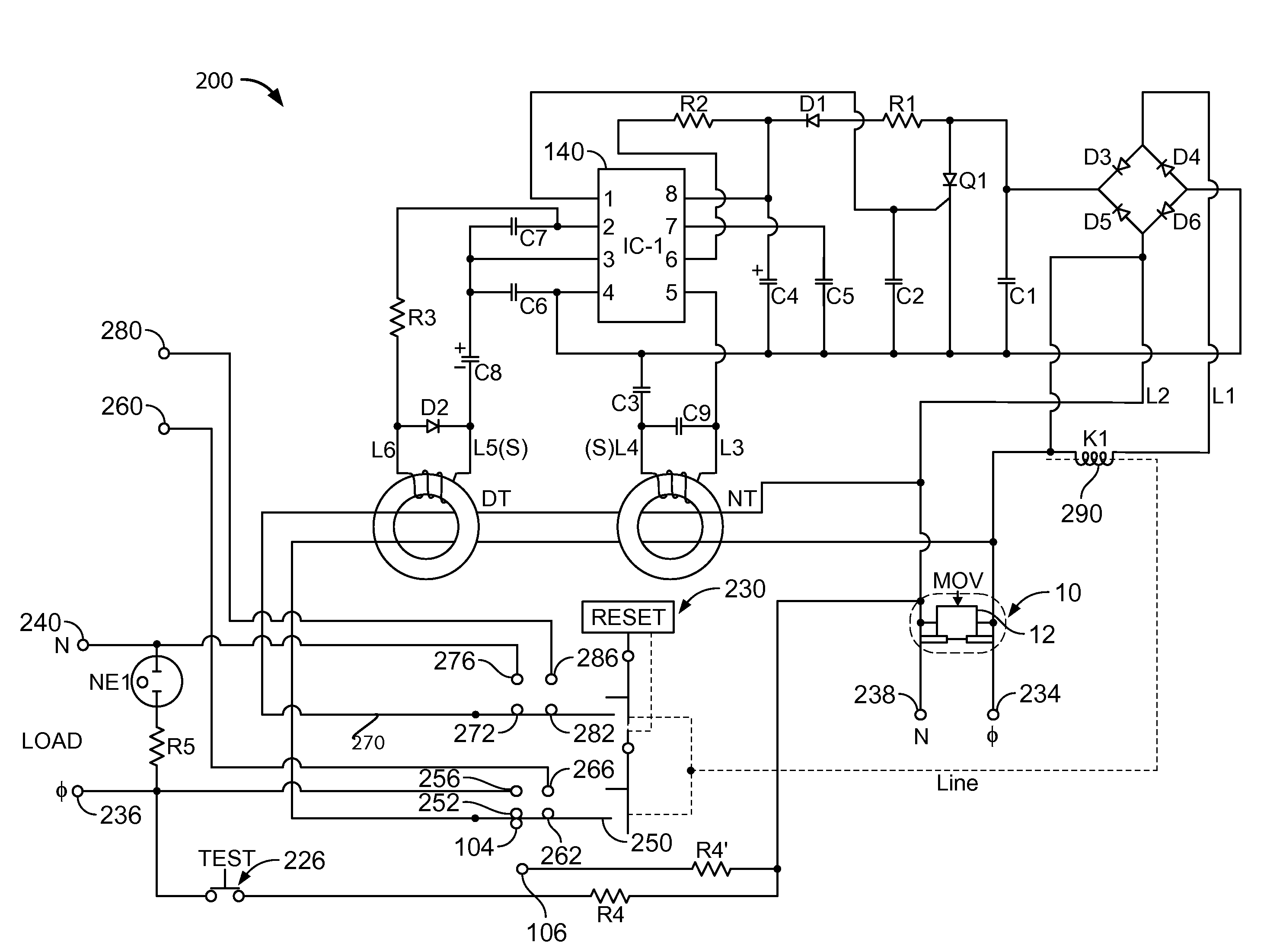
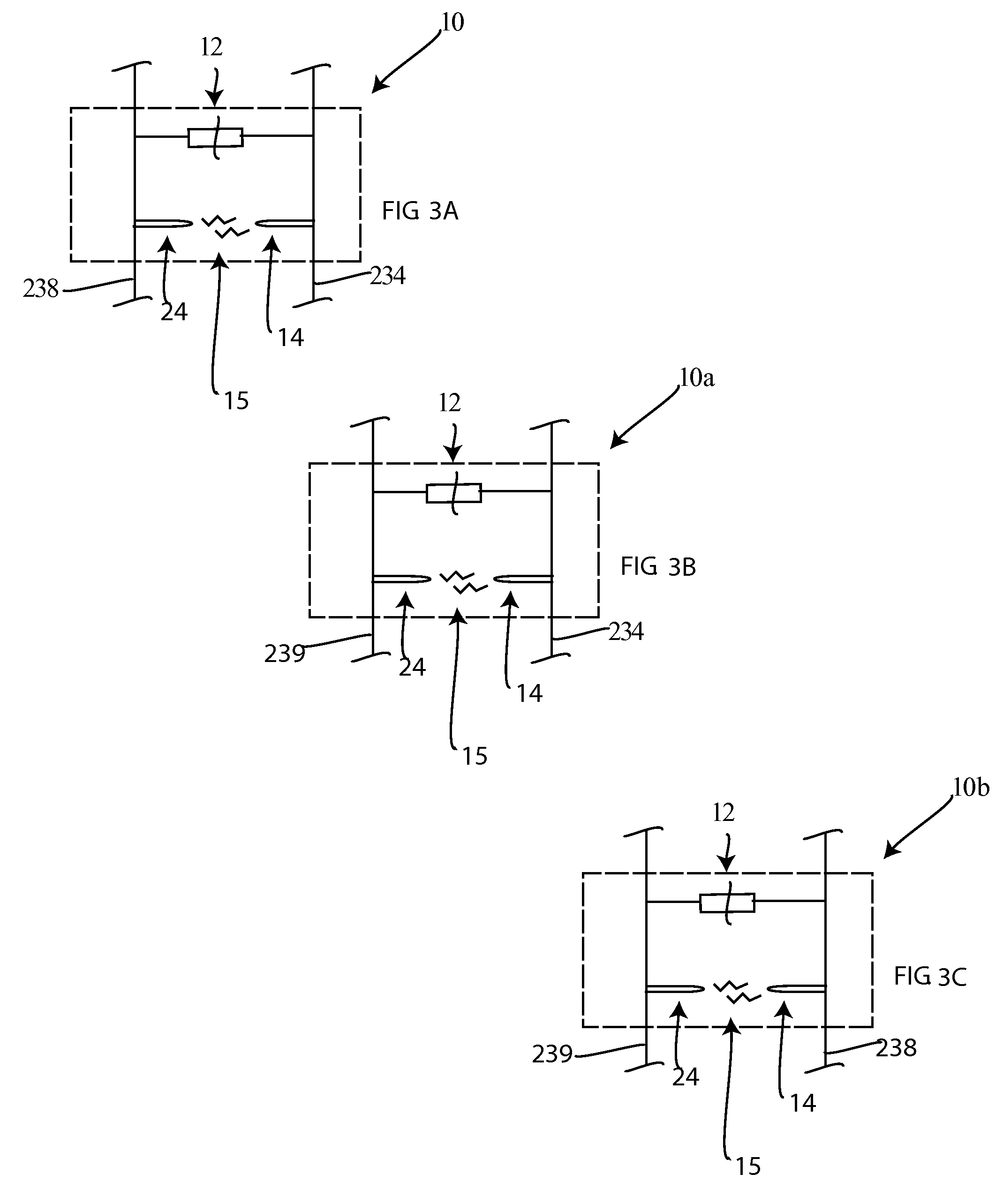
[0012]One embodiment of the invention relates to a fault circuit interrupter having an overvoltage device in the form of a MOV element that is connected such that it forms a MOV element in parallel with a spark gap. The MOV element is physically and electrically connected to a spark gap, wherein when the voltage rises to a level that provides a temperature below that at which the MOV will enter into its thermal runaway state the spark gap acts to allow this excess overvoltage to dissipate by extending across the spark gap, thereby relieving the heat pressure put on the MOV. In this case, the spark gap material is located on the a surface of the MOV and is electrically connected in parallel with the MOV. Generally, when a high voltage surge crosses the MOV, the components of the MOV heat up. The higher the voltage in the surge, the greater the heat created in the MOV. In addition, the higher the voltage of the surge, the greater the chance for the use of a spark gap which is adapted to react in the case of large voltage differences between two plates on an MOV forming a spark gap.
[0017]Thus, because these two components forming the overvoltage device, the MOV and the spark gap which are coupled in parallel, the MOV can be saved from any extreme overvoltage spikes due to the parallel positioning of the spark gap.

Problems solved by technology

In this case, during surges with high voltage conditions, a high voltage potential across an MOV would generate a relatively high current which would result in the heating and eventual destruction of the MOV.

Method used


Image

  • Overvoltage device with enhanced surge suppression
  • Overvoltage device with enhanced surge suppression
  • Overvoltage device with enhanced surge suppression

Examples


Embodiment Construction

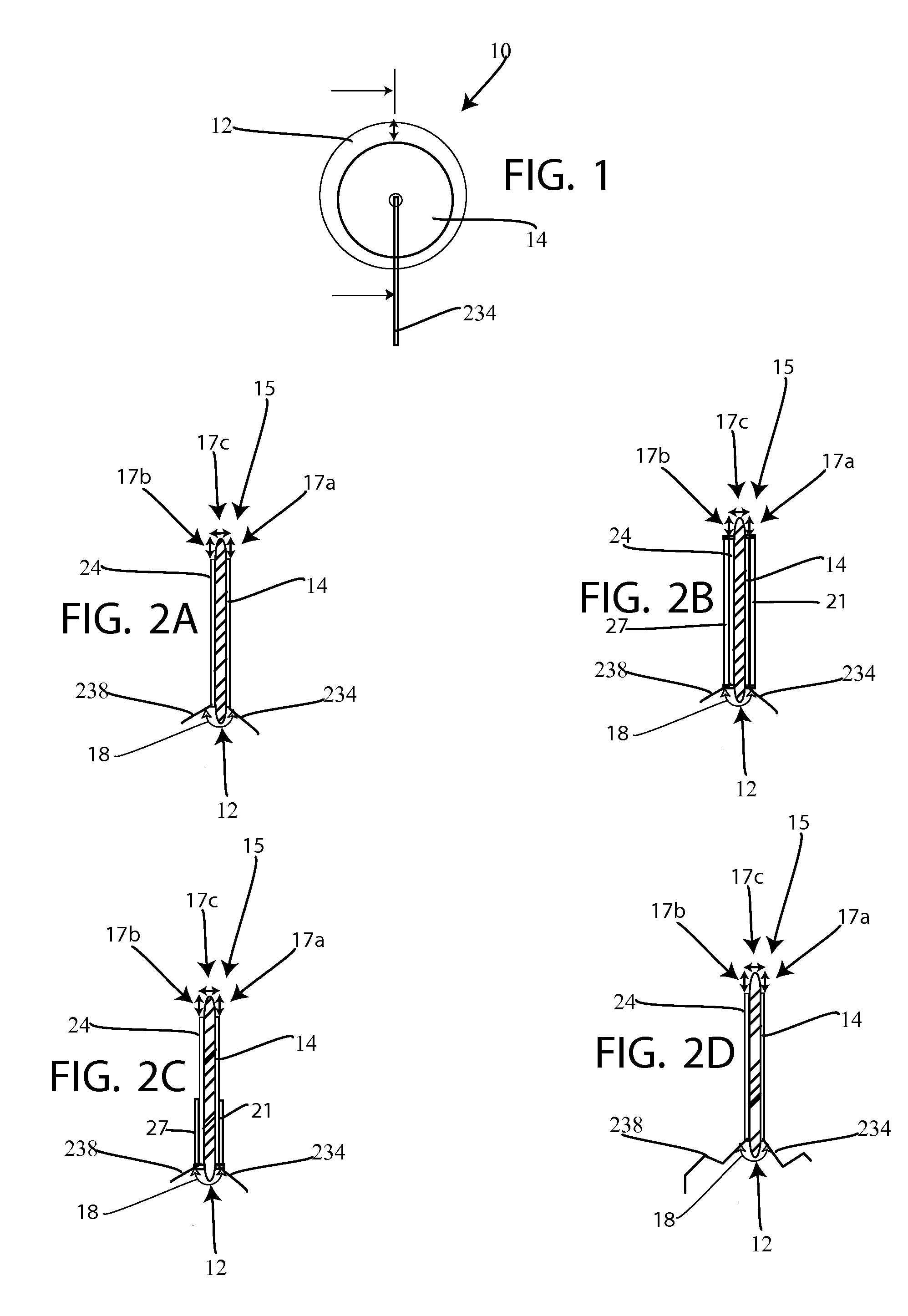
[0033]Referring to FIG. 1, there is shown a side view of an overvoltage protection device 10 which includes a MOV 12, having a body which can be of any shape but is shown here as disc shaped, and essentially as a solid disc. Coupled to this body is an electrically conductive material such as a conductive region in the form of a coating or plate 14 which is coupled to a first side or surface of MOV disc 12. MOV 12 having at least a first side have a surface and at least a second side having a surface. On the opposite or second side surface is a conductive coating or plate 24 (See FIG. 2A). Conductive coating or plate 24 is formed in a similar manner as conductive coating or plate 14.

[0034]For example, the first and second conductive regions are in the form of the metal coating or plate 14 and 24 that are coupled to MOV disc 12 via any known adhesive or via deposition of metal such as via any known deposition technique such as for example vapor deposition. Conductive region 14 is atta...


PUM


Abstract

An overvoltage device that is formed from a MOV device that is coupled in parallel with a spark gap. This device is coupled upstream from electronic components to protect these components from damage. For example, in one embodiment, the overvoltage device is coupled to a fault circuit interrupter such as a GFCI, across the phase and neutral lines to protect components of the GFCI from an overvoltage condition. In one embodiment the overvoltage device is formed as an MOV physically coupled to a spark gap wherein the MOV and the spark gap are electrically coupled across the phase line and the neutral line in parallel.

Description

BACKGROUND OF THE INVENTION[0001]The present invention relates generally to an overvoltage protection device comprising a metal oxide varistor (MOV) that can modify its operating characteristics to protect a ground fault circuit interrupter during the occurrence of an overload voltage surge.[0002]There is a need to protect AC line powered electronics from voltage spikes. One of the most popular methods of surge suppression is the metal oxide varistor (MOV). The surge suppression requirements for AC line powered electronics have increased in recent years. For example, UL testing now requires ground-fault circuit interrupters GFCIs to survive and function normally after several 6 kV, 3 kA voltage surges. It is also required that any surge suppression device for a GFCI must either survive, or self destruct in a safe manner, when a 10,000 amp current surge is applied. A MOV that is 14 or 20 mm in diameter is typically required to have the joule capacity to survive these high voltage, hi...

Claims


Application Information

Patent Timeline
IPC IPC(8): H02H3/22H01C7/10H02H3/20
CPCH01C7/10H02H9/044H02H9/043H01C7/108
Inventor CHAN, DAVID Y.BRADLEY, ROGER M.POWER, JOHN J.
Owner LEVITON MFG
Learn More