Vaporizing reservoir

a technology of vaporizer and reservoir, which is applied in the direction of steam generation using steam absorption, container discharging from pressure vessels, combustion air/fuel air treatment, etc., can solve problems such as user drawbacks, and achieve the effects of less prone to leakage, easy flavor change, and easy flavor chang

Inactive Publication Date: 2016-06-02
GOLDSTEIN GABRIEL MARC
View PDF40 Cites 113 Cited by
  • Summary
  • Abstract
  • Description
  • Claims
  • Application Information

AI Technical Summary

Benefits of technology

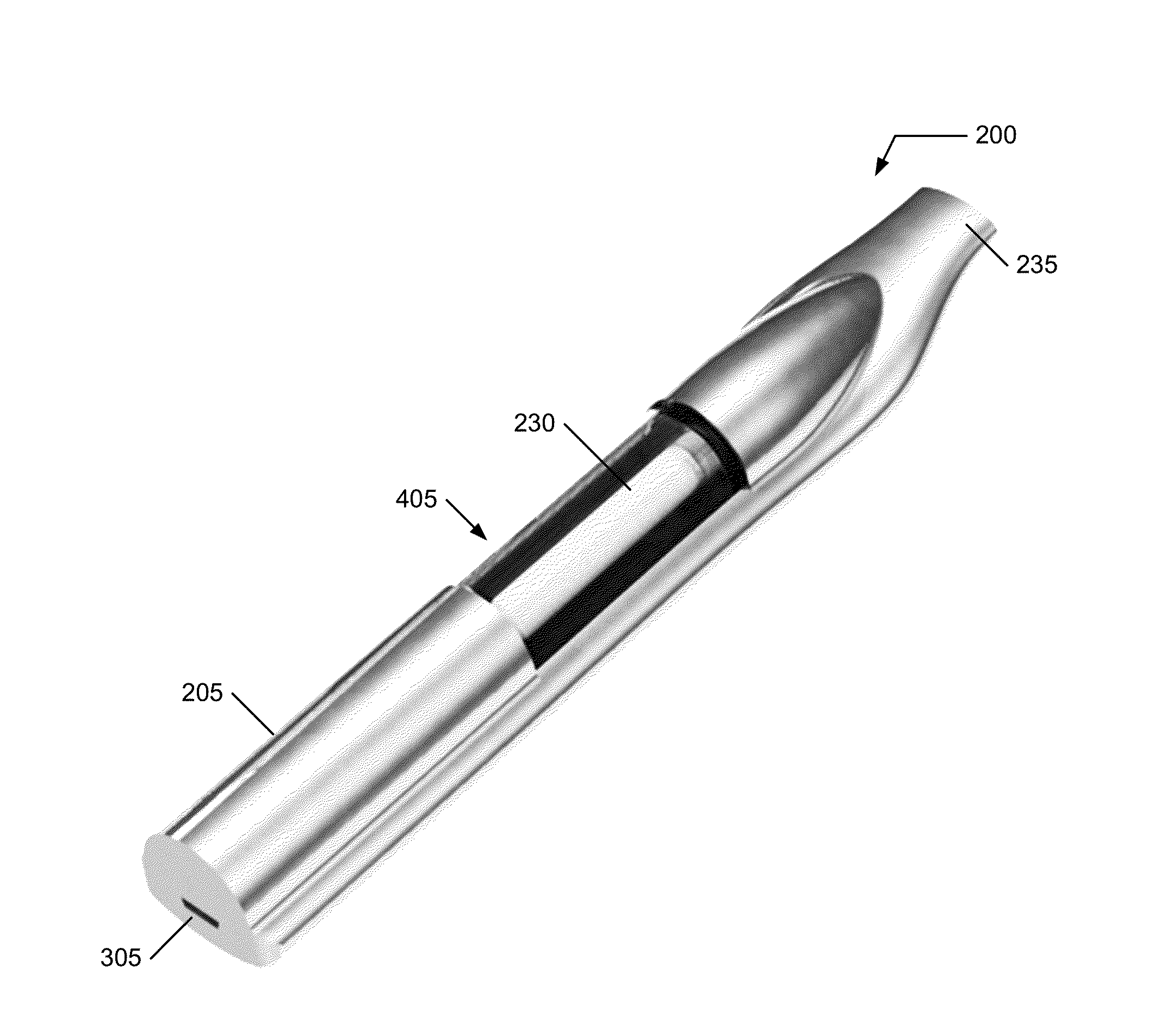
[0023]Vaporizing reservoirs, and vaporizing systems including the vaporizing reservoirs, may be made safer: 1) a consumable / cartridge style vaporizing reservoirs may either be sold pre-filled with e-liquid / oil or sterilized / empty sealed with a cap / tamper proof cap or with tape / foil or shrink wrapped for consumer protection; 2) there may be a sterilized / empty vaporizing reservoir for the botanical / organic and / or a wax medium that is sealed with a cap / tamper proof cap or with tape / foil or shrink wrapped for consumer protection; 3) the assembly is less prone to leaking during transport or when stored in a pocket, and 4) easier to change out flavors without the user getting the e-liquid or oil on the hands.
[0024]Vaporizing reservoirs, and vaporizing systems including the vaporizing reservoirs, may be made more convenient: 1) the vaporizing reservoir wick and coil assembly are an all in one incorporated assembly which makes the assembly less prone to leaking (leaking is a major complaint amongst many e-liquid users of conventional products on the market), 2) no replacement of wicks and coils are needed in the main body / vaporizing pens for they are all incorporated into the vaporizing reservoir, 3) change flavors with ease with no need to wait for one flavor to run out of the wick (or risking what is commonly referred to among users as a “dry hit” where the wick is being burned without vaporizing the liquid / oil), 4) alternative non-liquid vaporizing reservoirs may include the same form factor yet with a closed / built in grinder to make the particle size optimal for vaporization, 5) simple cartridge style assembly for easy to clean / remove old vaporized botanical / organic material.
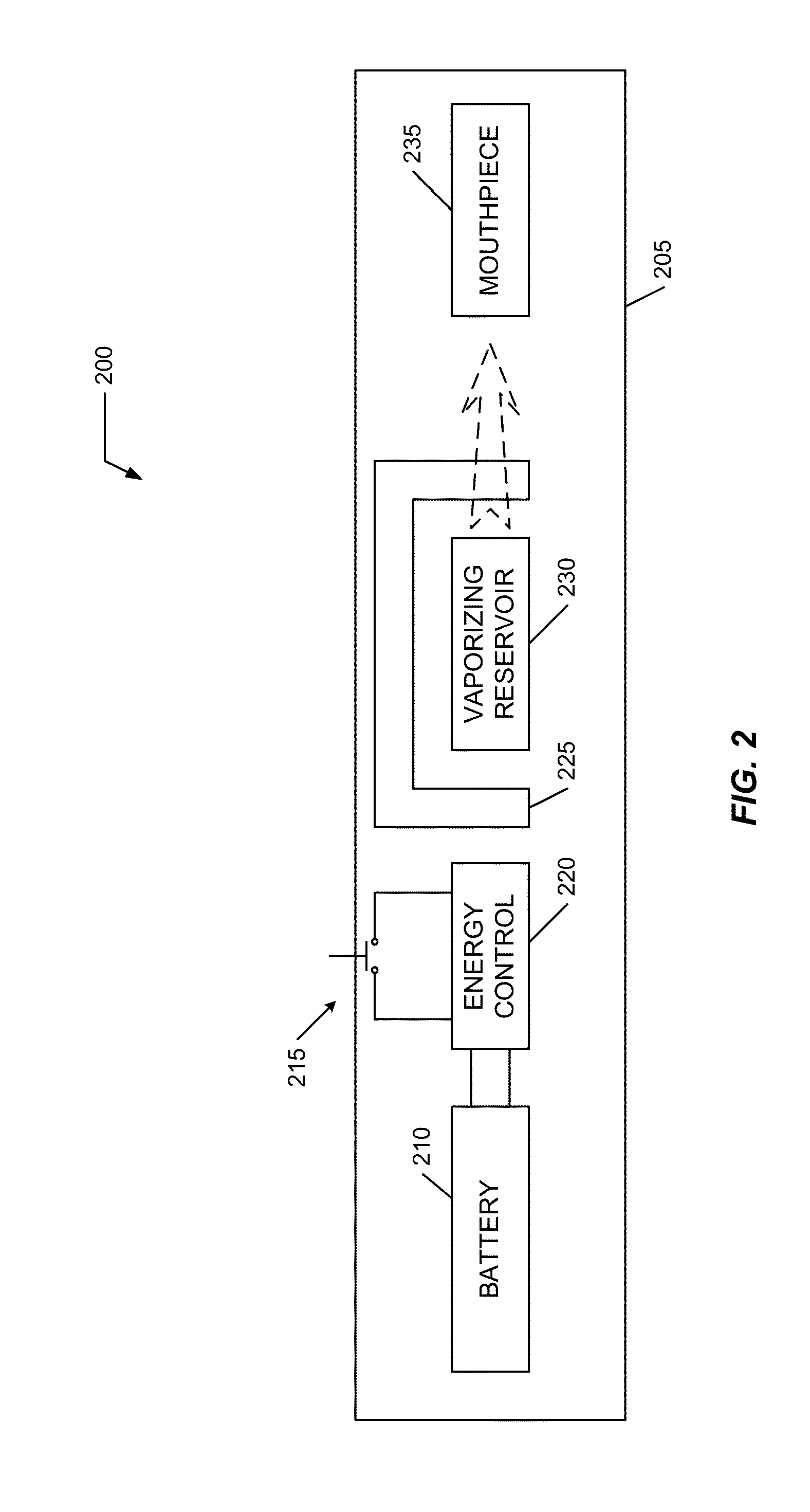
[0025]Vaporizing reservoirs, and vaporizing systems including the vaporizing reservoirs, may be made more effective: 1) the ability for the vaporizing reservoirs to either be powered by standard direct electrical connection / current or by induction, for example, allows optimum treatment for a particular material, 2) induction uses less energy which may allow for longer battery life or allow use of a smaller, lighter battery, 3) in combination with a vaporizing system which uses a PWM (pulse width modulation) to better control temperature and the rate of vaporization for any particular material (and which may be tuned / adjusted for a particular material as the vaporizing reservoir is exchanged for another one having a different material with different optimization parameters.

Problems solved by technology

This fundamental structure and operation leads to the drawbacks encountered by users.

Method used


Image

  • Vaporizing reservoir
  • Vaporizing reservoir
  • Vaporizing reservoir

Examples


Embodiment Construction

[0058]Embodiments of the present invention provide a system and method for a user experience with respect to vaporizers and the like. The following description is presented to enable one of ordinary skill in the art to make and use the invention and is provided in the context of a patent application and its requirements.

[0059]Various modifications to the preferred embodiment and the generic principles and features described herein will be readily apparent to those skilled in the art. Thus, the present invention is not intended to be limited to the embodiment shown but is to be accorded the widest scope consistent with the principles and features described herein.

DEFINITIONS

[0060]Unless otherwise defined, all terms (including technical and scientific terms) used herein have the same meaning as commonly understood by one of ordinary skill in the art to which this general inventive concept belongs. It will be further understood that terms, such as those defined in commonly used diction...


PUM

PropertyMeasurementUnit
gassing temperatureaaaaaaaaaa
solutionaaaaaaaaaa
electrical energyaaaaaaaaaa

Abstract

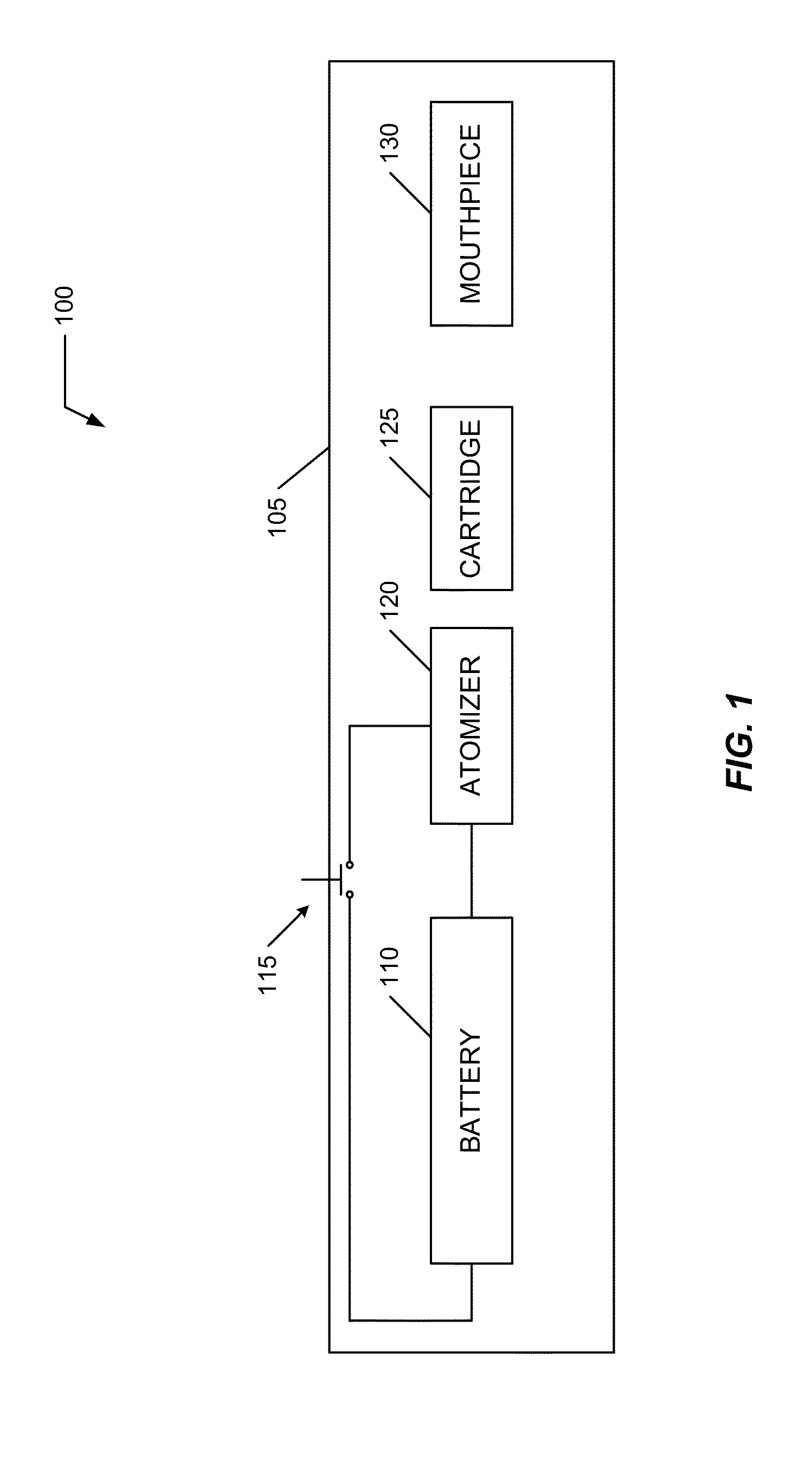
A vaporizing reservoir including a containment vessel having a first shaft port exposed to ambient and one or more sidewalls defining a body portion having an interior cavity and a vaporizing portion communicated to the interior cavity; an inductive coil disposed within the vaporizing portion, the inductive coil electrically disconnected outside of the containment vessel and configured for inductive heating; and an air shaft communicated to the vaporizing portion and extending to the first shaft port. Fluid or solid material may be present in the interior cavity for vaporization. For fluid material, a wick may be included with the inductive coil to facilitate communication of the material to the inductive coil. An exterior inductive coil heats the inductive coil within the vaporizing portion and vaporizes the material communicated to the interior inductive coil. Vapor from the heated interior inductive coil is extracted through the air shaft.

Description

CROSS REFERENCE TO RELATED APPLICATIONS[0001]This application claims benefit of U.S. Patent No. 62 / 086,519, the contents of which is hereby expressly incorporated in its entirety for all purposes.COPYRIGHT OF INVENTION[0002]A portion of the disclosure of this patent document contains material to which a claim for copyright is made. The copyright owner has no objection to the facsimile reproduction by anyone of the patent document or the patent disclosure, as it appears in the Patent and Trademark Office patent file or records, but reserves all other copyright rights whatsoever.FIELD OF THE INVENTION[0003]The present invention relates generally to vaporizers used in cooperation with material, for example botanical material, and more specifically, but not exclusively, to a vaporizing reservoir, a vaporizer using the vaporizing reservoir, and methods of vaporizing material using the vaporizing reservoir.BACKGROUND OF THE INVENTION[0004]The subject matter discussed in the background sec...

Claims


Application Information

Patent Timeline
Patent Type & Authority Applications(United States)
IPC IPC(8): A24F47/00H05B3/00H05B6/36A24F40/10A24F40/42A24F40/465A24F40/485
CPCA24F47/008H05B3/0014H05B6/36H05B3/16H05B6/108A24F40/465A24F40/10A24F40/42A24F40/485
Inventor GOLDSTEIN, GABRIEL MARCSCHOUTEN, PIETER HANSHART, RICHARD DALE
Owner GOLDSTEIN GABRIEL MARC
Why Eureka
Try Eureka