Dynamic channel allocation method and dynamic channel allocation apparatus

a dynamic channel and allocation method technology, applied in the direction of electrical devices, network planning, selection arrangements, etc., can solve the problems of not being able to effectively use, not being able to achieve effective use, not only affecting the availability of channels, but also affecting the time delay of exchanging messages. , to achieve the effect of ensuring fairness among base stations and uniqueness of channel availability

Inactive Publication Date: 2007-06-07
FUJITSU LTD
View PDF4 Cites 19 Cited by
  • Summary
  • Abstract
  • Description
  • Claims
  • Application Information

AI Technical Summary

Benefits of technology

[0041] According to the fourteenth dynamic channel allocation method, the latest request channel information can be informed to the adjacent base stations promptly. According to the fifteenth dynamic channel allocation method, determination on whether channels are available can be made promptly. According to the sixteenth dynamic channel allocation method, availability of channels can be judged uniquely. According to the seventeenth dynamic channel allocation method, fairness among the base stations can be ensured. According to the eighteenth dynamic channel allocation method, there is relatively a good chance of receiving channel allocation.

Problems solved by technology

In these technologies, however, the voice traffic at low speed and a constant rate is the target, thus these technologies are not suitable for effectively using radio resource to transmit a data traffic with a strong burst property.
For this reason, the calculation amount for deriving the MIS becomes large as the network expands, and, since the device for executing such calculation is required at the center of the network, not only is a calculation delay significant, but also a time delay for exchanging message.
In the LP base method, the calculation amount for deriving the MIS becomes large as the network expands, since the device for executing such calculation is required at the center of the network, not only is a calculation delay significant, but also a time delay for exchanging message.

Method used


Image

  • Dynamic channel allocation method and dynamic channel allocation apparatus
  • Dynamic channel allocation method and dynamic channel allocation apparatus
  • Dynamic channel allocation method and dynamic channel allocation apparatus

Examples


first embodiment

Basic Pattern

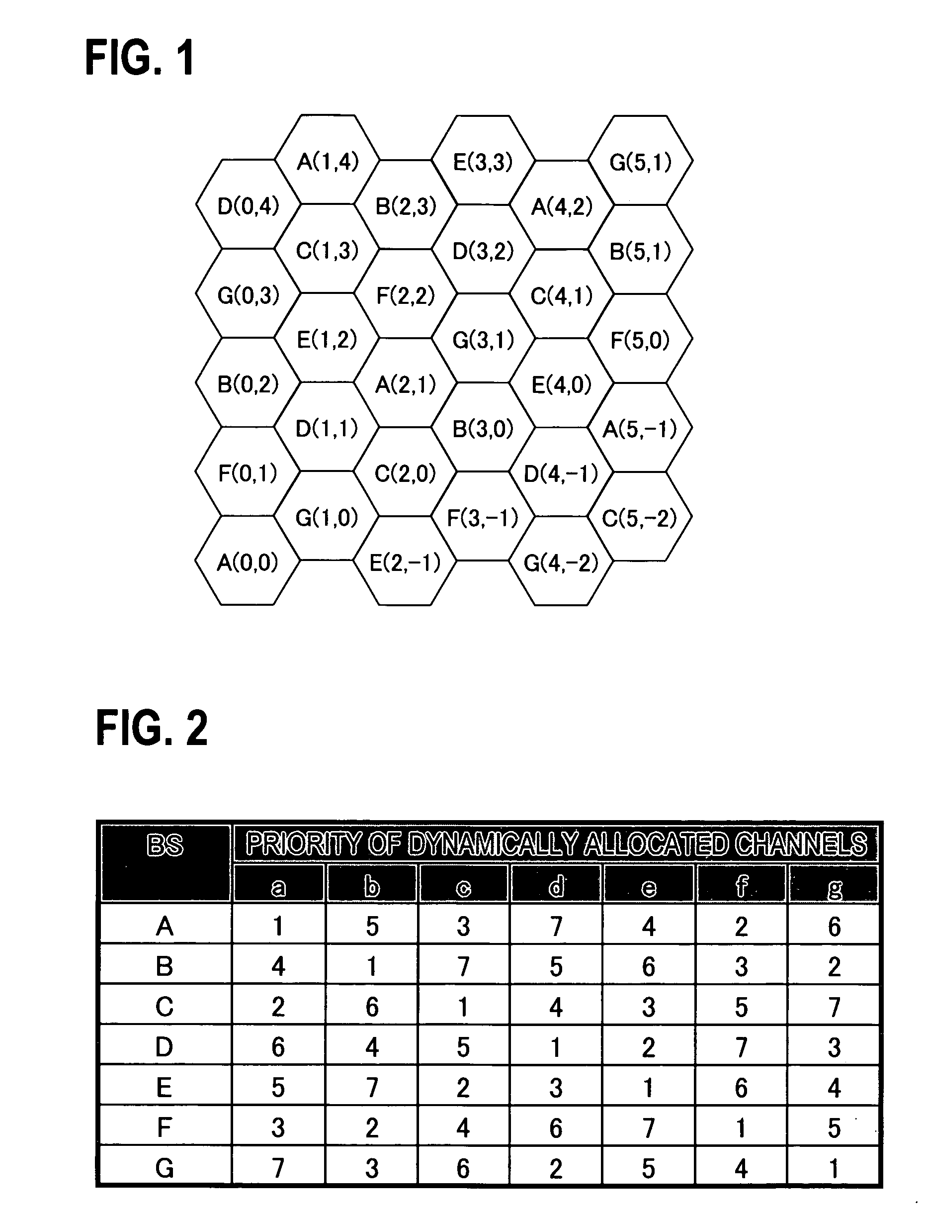
[0068]FIG. 1 is a figure showing an example of a wireless communication network. In FIG. 1, X(v, u) (X=A, B, . . . , G, v, u are coordinate axes) is an identifier of a base station, and a hexagon indicates a cover area of the base station. A through G indicate a base station group comprising base stations which do not mutually interfere with one another. For example, for a base station A(2, 1), adjacent base stations interfering with the base station A(2, 1) are base stations B(3, 0), C(2, 0), D(1, 1), E(1, 2), F(2, 2), and G(3, 1) surrounding the base station A(2, 1). The base station A(2, 1) is not placed adjacent to other base stations A(0, 0), A(5, 1), A(4, 2), and A(1, 4) that are in the base station A group, and the base stations in the base station A group are placed in position where they do not interfere with one another. It should be noted here that “BS” means a base station.

[0069]FIG. 2 is a figure showing an example of a priority table defining the priorit...

second embodiment

Repetition of Publication

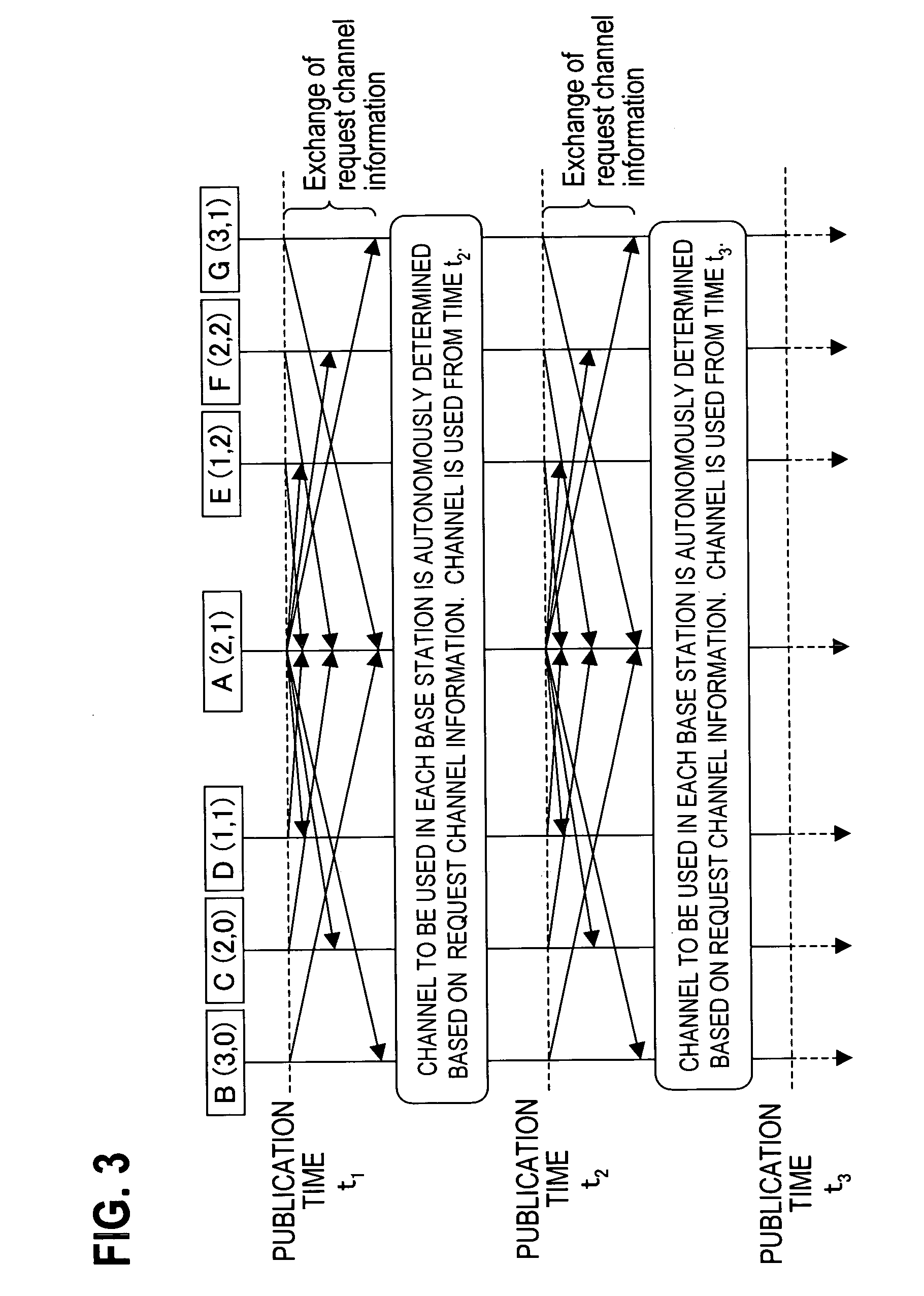
[0094] In FIG. 3, exchange of the request channel information is carried out once. However, this exchange performance cannot respond to a situation in which an available channel to an adjacent base station changes depending on the request channel information of an adjacent base station of the adjacent base station.

[0095] For example, the wireless communication network configured in FIG. 1 and FIG. 2 is considered as an example. FIG. 12 is a figure showing an example of the wireless communication network, and is same as FIG. 1, except that the base station A(2, 1) is colored in FIG. 12.

[0096] In FIG. 12, when the base station A(2, 1) is in an idle state (no traffic) and an adjacent base station uses a channel a (high-priority channel for the base station A), it is considered whether G(3, 1), which takes this channel as the lowest priority, can use this channel. For example, the priority on the channel is higher for B(3, 0) than G(3, 1), thus, when B(3, 0) ...

third embodiment

Time Information

[0107] In the above first and second embodiments, availability / unavailability of channels is judged on the basis of the publication time in which the base stations synchronize. Therefore, if transmission of a traffic is completed by the next publication time, new channel allocation is not performed, thus channels cannot be used effectively. Moreover, in the second embodiment, even when the request channel information, which indicates that the channel is determined to be unavailable, is informed to the adjacent base stations after the channel is used, when another base station starts using the channel the request channel information needs to be exchanged again with the adjacent base stations.

[0108] In the third embodiment, therefore, time information such as a channel starting time and time in which the channel is used is contained in the request channel information, and the request channel information is informed to the adjacent base stations.

[0109]FIG. 16 is a fi...


PUM


Abstract

(1) Base stations are divided into base station groups which do not mutually interfere with one another. (2) Priorities of the use of channels are set for each base station group, and each base station holds a priority table showing the priorities of the use of channels. (3) Each base station derives a channel to request, and informs about the channel to adjacent base stations. (4) When the requested channel of the base station overlaps with a requested channel of the adjacent base station, each base station refers to the priority table and autonomously judges whether the requested channel can be used or not. Therefore, it is no longer necessary to wait for a response to the requested message or to confirm with the adjacent base stations regarding the availability of channels, and reduction of the throughputs and prompt channel allocation are possible.

Description

CROSS-REFERENCE TO RELATED APPLICATIONS [0001] This application is based upon and claims the benefit of priority from the prior Japanese Patent Application No.2005-348858, filed on Dec. 2, 2005, the entire contents of which are incorporated herein by reference. BACKGROUND OF THE INVENTION [0002] 1. Field of the Invention [0003] The present invention relates to a channel allocation method and apparatus in a wireless communication system, and particularly to a dynamic channel allocation method and a dynamic channel allocation apparatus for dynamically allocating channels in response to increase / decrease of traffic. [0004] 2. Description of the Related Art [0005] Effective allocation of channels is carried out in order to effectively use a wireless resource. Here, “channel” is defined by time, frequency, or a combination thereof. It is defined by a code in the CDMA technology. [0006]“Channel Assignment Schemes for Cellular Mobile Telecommunication Systems: A Comprehensive Survey” (I. K...

Claims


Application Information

Patent Timeline
Patent Type & Authority Applications(United States)
IPC IPC(8): H04Q7/20H04W16/10
CPCH04W16/10H04W72/0406H04W72/0413H04W72/082H04W92/20H04W72/21H04W72/20H04W72/541
Inventor OKUDA, MASATOHATANO, TAKASHI
Owner FUJITSU LTD
Why Eureka
Try Eureka