Double clutch transmission
a transmission and clutch technology, applied in mechanical equipment, transportation and packaging, gearing, etc., can solve the problems of high torque load on all components which follow in the force flux, sharp increase, etc., and achieve the effect of reducing wear
- Summary
- Abstract
- Description
- Claims
- Application Information
AI Technical Summary
Benefits of technology
Problems solved by technology
Method used
Image
Examples
first embodiment
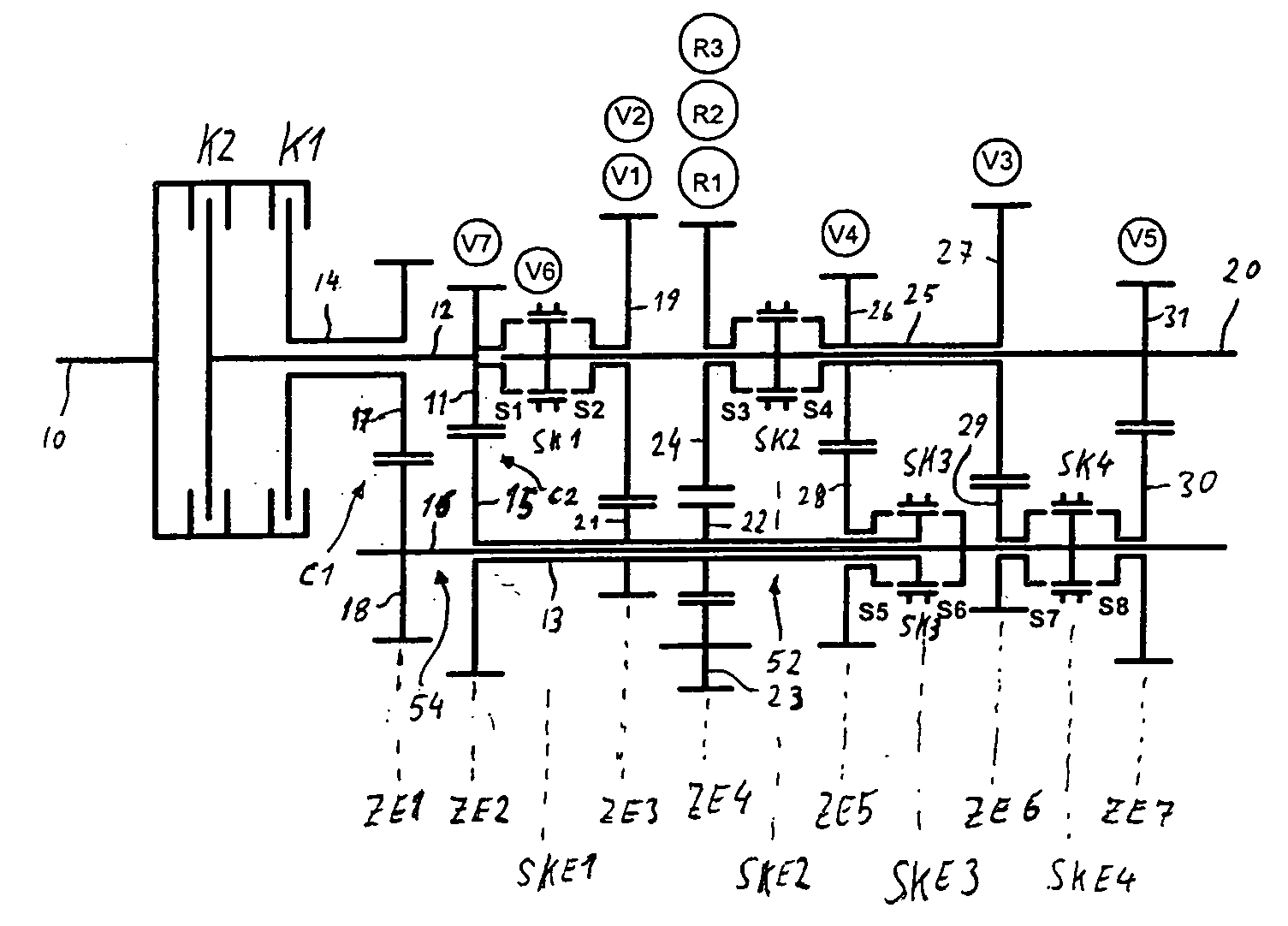
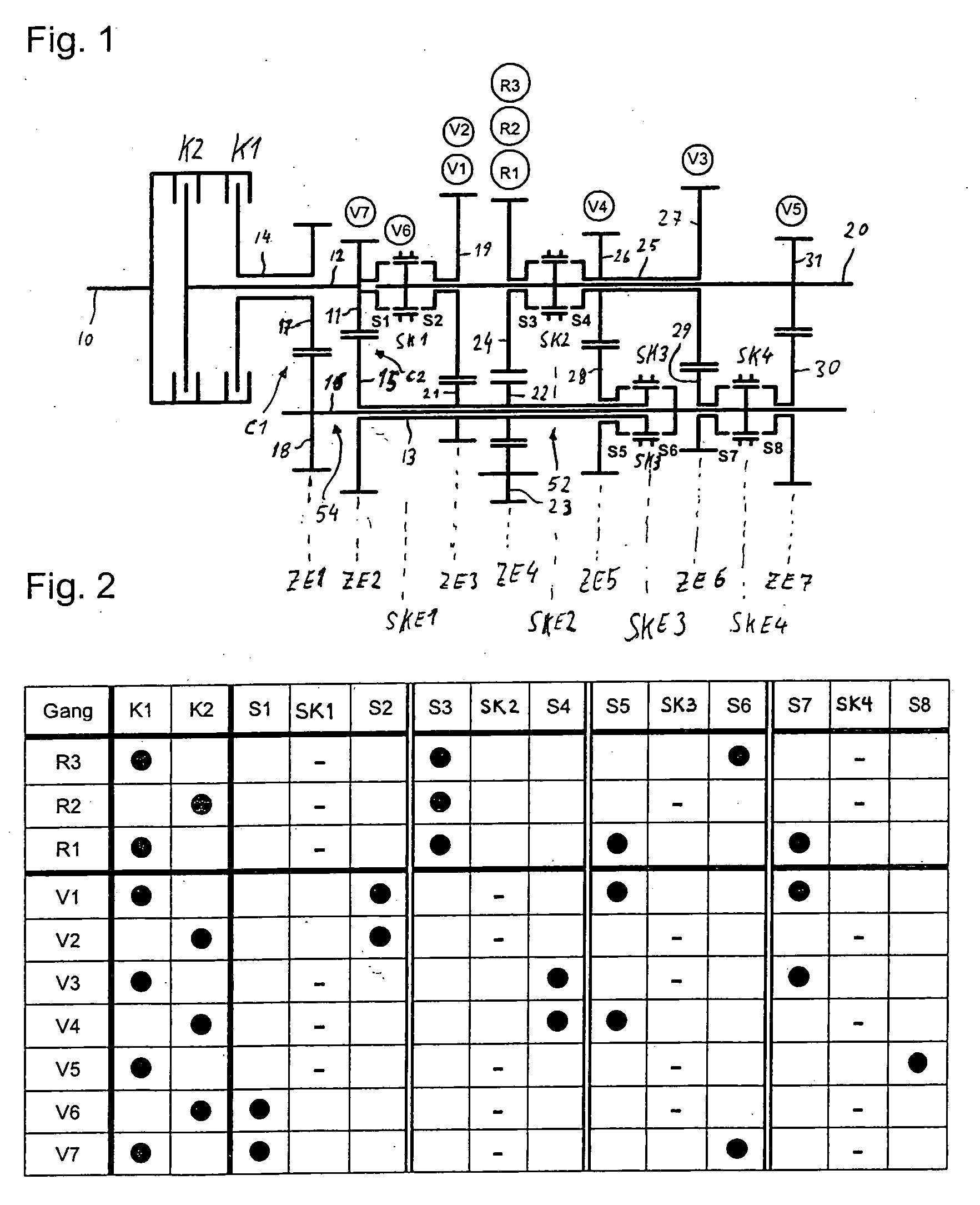
[0052]FIG. 1 shows a double clutch transmission in a first embodiment, which is used in a rear drive or multi-axle drive of a motor vehicle, the engine and double clutch transmission of which are installed longitudinally in the direction of travel. This motor vehicle may be, in particular, a high-torque passenger car or a commercial vehicle.
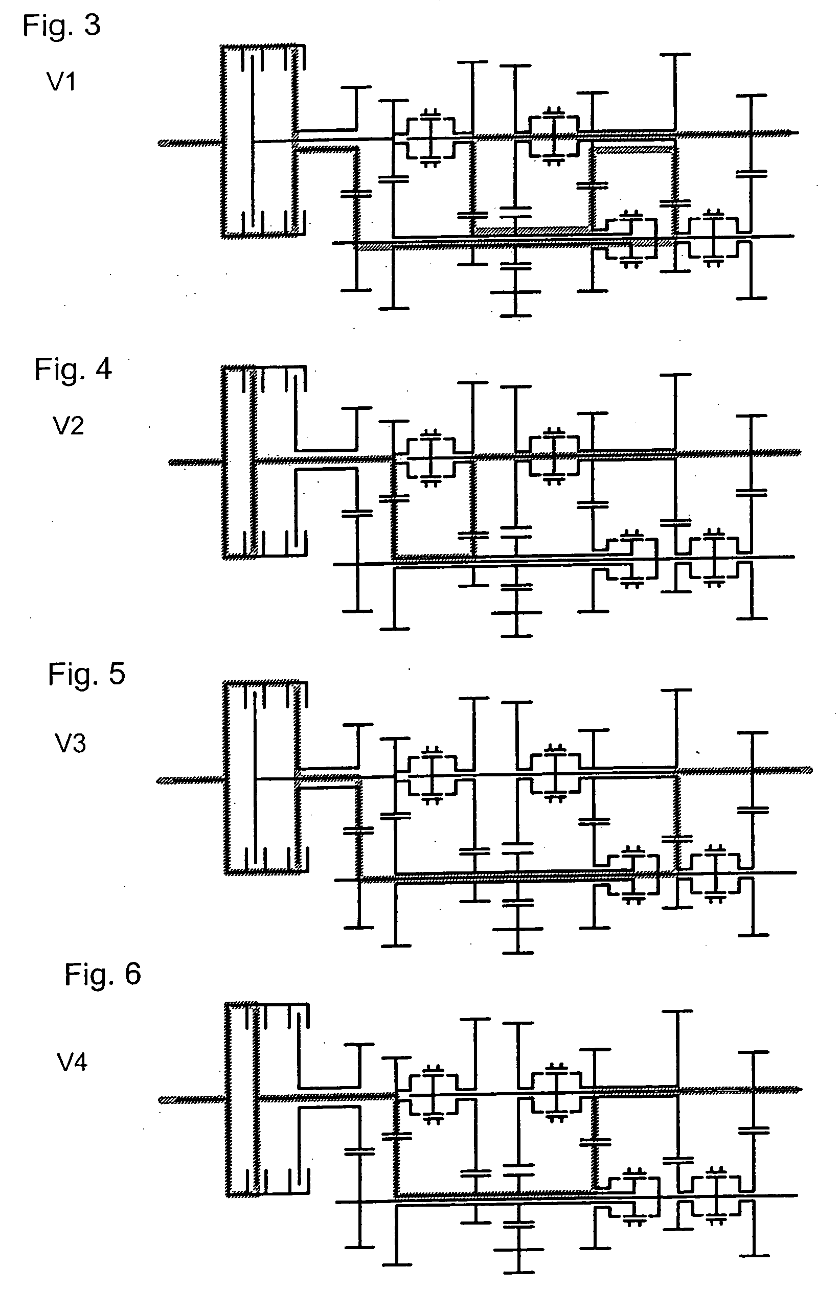
[0053] In the double clutch transmission, an input shaft 10 is connected to a transmission output shaft 20 by means of a first part transmission 54 and a second part transmission 52. The two part transmissions 52 and 54 are arranged parallel to one another in the power flux. The part transmissions 52, 54 possess in each case a power-shift friction clutch K1, K2 and in each case an intermediate shaft 12, 14, of which the first intermediate shaft 14 is designed as a radially outer hollow shaft and the second intermediate shaft 12 as a radially inner intermediate shaft 12. The intermediate shafts 12, 14 are arranged [0054] concentrically with respec...
second embodiment
[0216]FIG. 13 shows a double clutch transmission in a
[0217] The construction of this double clutch transmission is identical, from the front as far as the third shift clutch plane SKE3 to the first embodiment, and therefore reference to the latter is made here.
[0218] However, a fourth shift clutch SK4 is arranged coaxially with respect to the transmission input shaft 20. By means of this shift clutch SK4, on the one hand, in a position S7, a gearwheel 27 arranged rotatably and coaxially on the second hollow shaft 25 in a sixth gearwheel plane ZE6 can be connected fixedly in terms of rotation to the hollow shaft 25. On the other hand, in a position S8, an axially adjacent gearwheel 31 arranged rotatably and coaxially on the transmission output shaft 20 in a seventh gearwheel plane ZE7 can be connected fixedly in terms of rotation to the transmission output shaft 20.
[0219] A fixed wheel 29 arranged coaxially and fixedly in terms of rotation on the inner shaft 16 meshes with the gear...
third embodiment
[0222]FIG. 15 shows a double clutch transmission in a
[0223] The construction of this double clutch transmission is identical, from the front as far as the third shift clutch plane SKE3, to the first and the second embodiment, and therefore reference is made here, in this respect, to both of these. As regards the seventh gearwheel plane ZE7, reference is made to the second embodiment since this is identical in the region of the seventh gearwheel plane ZE7.
[0224] In contrast to the preceding embodiments, only two intermeshing gearwheels are arranged in the gearwheel plane ZE4 assigned to the single reverse gear R1. One of these two gearwheels is a loose wheel 22 which is arranged rotatably and coaxially on the first hollow shaft 13. The other gearwheel is an intermediate wheel 23 which, in contrast to the preceding exemplary embodiments, does not have a direct output to a gearwheel in the fourth gearwheel plane ZE4, but, by means of a second intermediate wheel 33, has an output via a...
PUM
 Abstract
Description
Claims
Application Information
 - R&D
- Intellectual Property
- Life Sciences
- Materials
- Tech Scout
- Unparalleled Data Quality
- Higher Quality Content
- 60% Fewer Hallucinations
Browse by: Latest US Patents, China's latest patents, Technical Efficacy Thesaurus, Application Domain, Technology Topic, Popular Technical Reports.
© 2025 PatSnap. All rights reserved.Legal|Privacy policy|Modern Slavery Act Transparency Statement|Sitemap|About US| Contact US: help@patsnap.com


