Lathe

a technology of lathes and backs, applied in the field of lathes, can solve the problems of serious affecting processing accuracy and safety, correspondingly increasing the forward-backward dimension of the machine, and affecting the processing, so as to reduce the amount of chips, reduce the forward-backward dimension of the entire lathe, and reduce the forward-backward dimension

Active Publication Date: 2010-05-18
MURATA MASCH LTD
View PDF26 Cites 1 Cited by
  • Summary
  • Abstract
  • Description
  • Claims
  • Application Information

AI Technical Summary

Benefits of technology

[0004]It is an object of the present invention to provide a lathe which accumulates a reduced amount of chips on a slide member such as a cross slide which serves as a tool holder mounting base and which enables a reduction in the forward-backward dimension of the entire lathe. It is another object of the present invention to eliminate the need for a chip dropping space located in front of the slide member, enabling a further reduction in forward-backward dimension. It is yet another object of the present invention to fix the position of processing means in the forward-backward direction, enabling a further reduction in forward-backward dimension. It is still another object of the present invention is to compactly mount a tool and a tool holder on the slide member.
[0005]The present invention provides a lathe comprising a spindle that rotatably supports a workpiece and processing means located in front of the spindle, the lathe moving one or both of the spindle and the processing means forward and backward to execute machining on the workpiece, wherein the processing means comprises a tool, a tool holder that supports the tool, and a slide member which is slidable in a lateral direction and which supports the tool holder, the slide member having an inclined surface that is positioned lower as the inclined surface approaches the spindle and on which the tool holder is mounted and supported. In this configuration, the tool holder is mounted and supported on the inclined surface that is positioned lower as the inclined surface approaches the spindle of the slide member. Consequently, chips generated when the workpiece supported by the spindle is machined using the tool fall downward along the inclined surface of the slide member. This makes the chips unlikely to accumulate on the slide member, eliminating the adverse effect of the chips on the processing. Further, the tool holder mounting surface of the slide member is inclined. This ensures that the tool holder mounting surface is long enough to mount the tool holder thereon in spite of the short forward-backward dimension of the slide member. This enables a reduction in the forward-backward dimension of the slide member and a corresponding reduction in the forward-backward dimension of the lathe.
[0006]In the present invention, the lathe may have a machine body cover comprising an integral cover or a plurality of partial covers which cover the spindle and the processing means, and a front portion of the machine body cover may be mounted in tight contact with a front surface of a bed member supporting the slide member. This configuration eliminates the need for the space between the bed member supporting the slide member and the front portion of the machine body cover. This enables a reduction in the forward-backward dimension of the lathe. The inclined surface of the slide member is positioned lower as the inclined surface approaches the spindle. Chips fall toward the spindle side, that is, rearward along the inclined surface. This eliminates the need to provide a chip dropping space in front of the slide member. Thus, as described above, the front portion of the machine body cover can be mounted in tight contact with the front surface of the bed member.

Problems solved by technology

The chips accumulated on the cross slide may affect the processing.
Particularly in automated facilities, the accumulated chips may seriously affect processing accuracy and safety.
However, disadvantageously, the provision of the chip dropping space correspondingly increases the forward-backward dimension of the machine.

Method used


Image

  • Lathe
  • Lathe
  • Lathe

Examples


Embodiment Construction

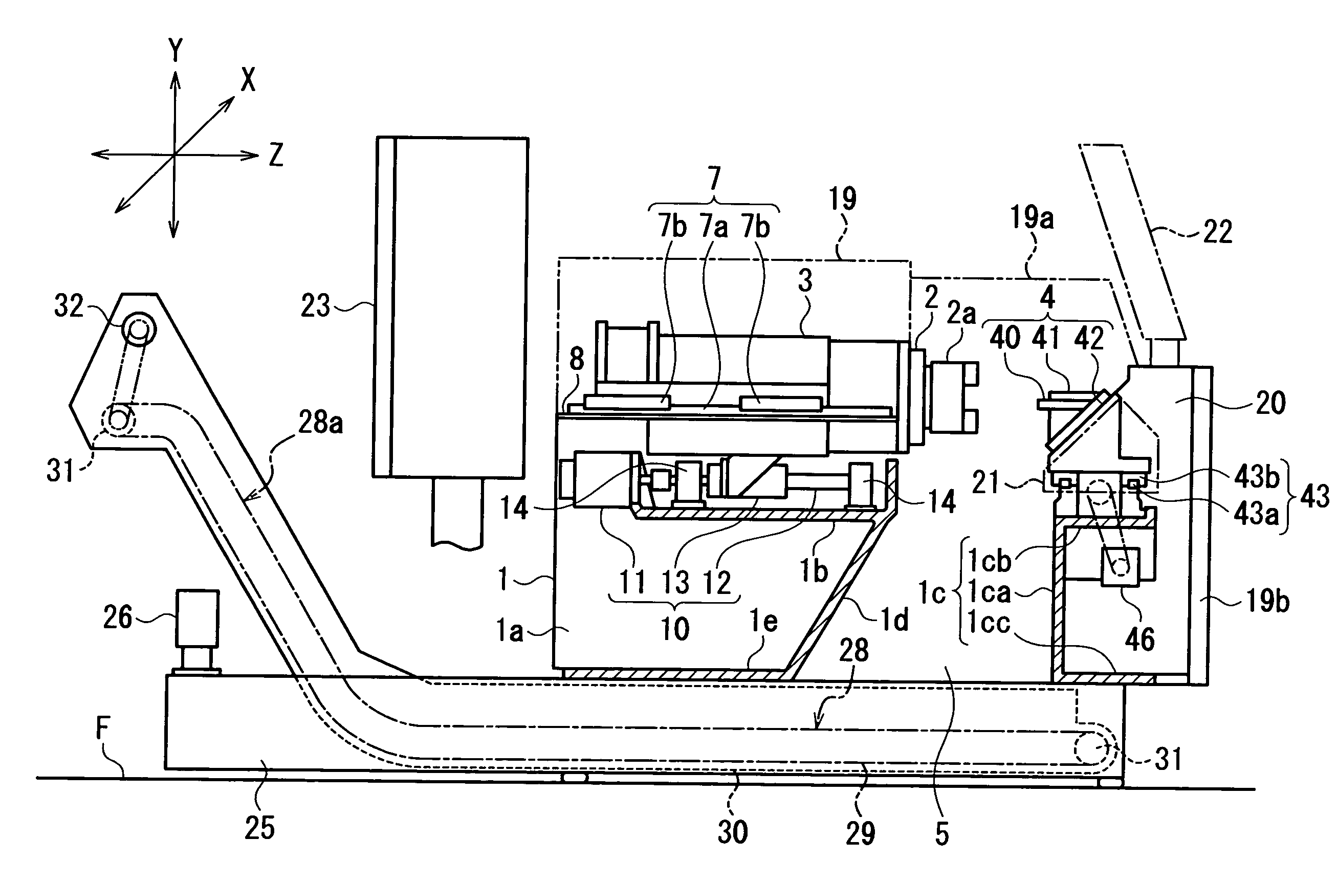
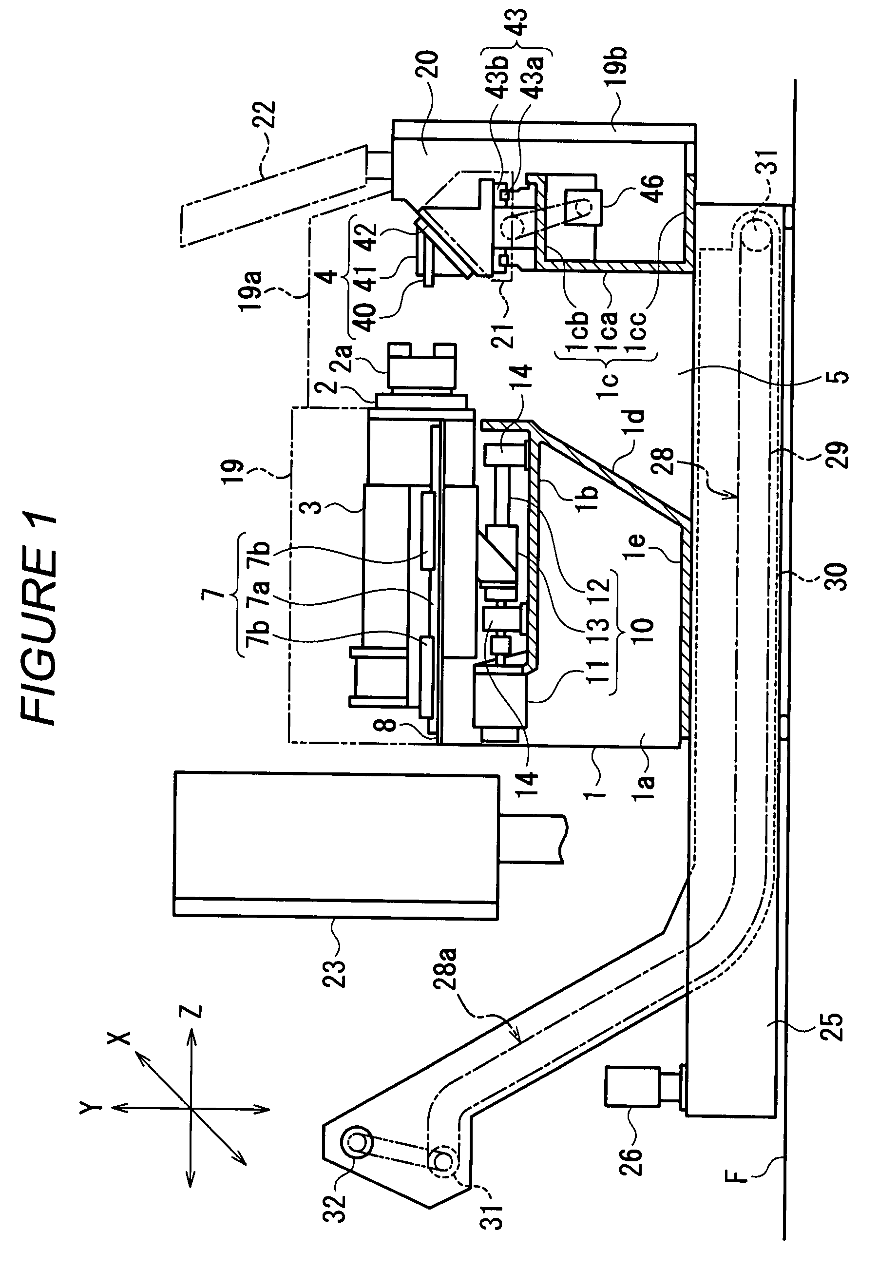
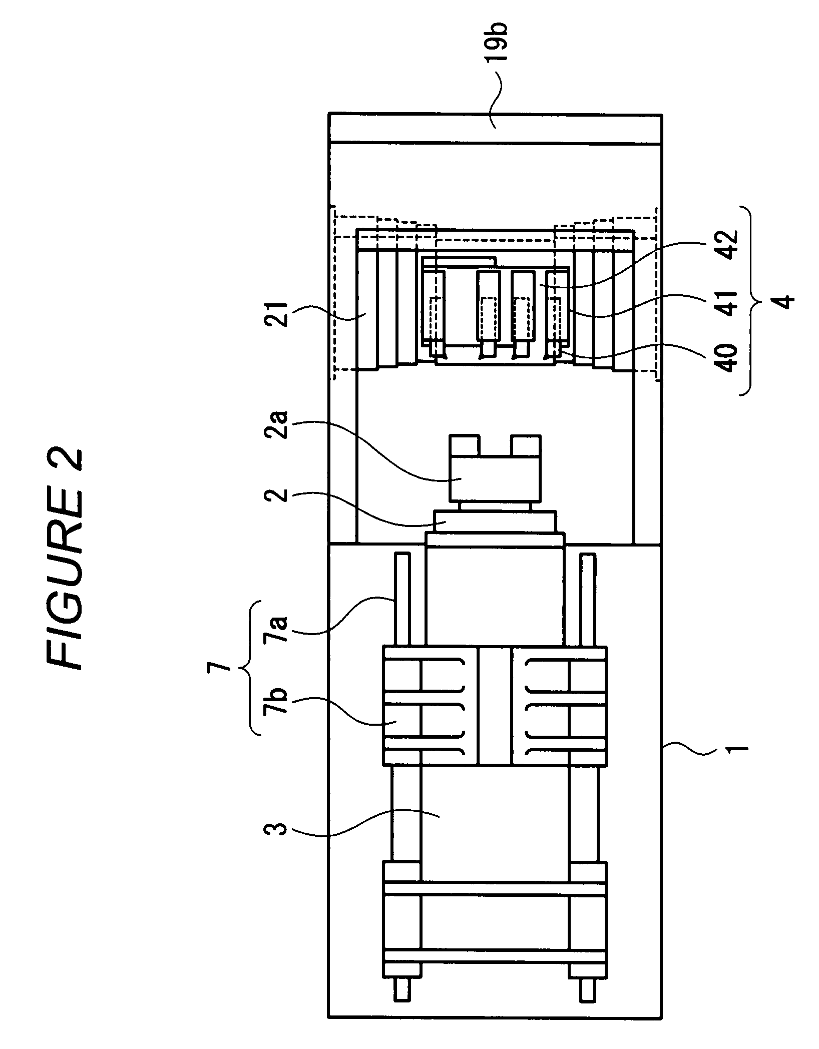
[0019]An embodiment of the present invention will be described with reference to FIG. 1 to FIG. 4. The lathe has a headstock 3 supporting a spindle 2 and installed on a bed 1 so as to be movable forward and backward (the direction of a Z axis). The spindle 2 faces in the forward-backward direction (the direction of a Z axis). A spindle chuck 2a is provided at a front end of the spindle 2. A processing means 4 is provide in front of the spindle 2.

[0020]The bed 1 is shaped like a box having a pair of opposite side plate portion 1a, a top plate portion 1b provided in the rear of the side plate portions 1a between upper ends of the side plate portions 1a, and a front plate portion 1c provided between front ends of the opposite side plate portions 1a. The front plate portion 1c has a vertical upright portion 1ca, an upper end horizontal portion 1cb horizontally extended forward from an upper end of the vertical upright portion 1ca, and a lower end horizontal portion 1cc horizontally exte...


PUM

PropertyMeasurementUnit
processing accuracyaaaaaaaaaa
shapeaaaaaaaaaa
heightaaaaaaaaaa

Abstract

The present invention provides a lathe which accumulates a reduced amount of chips on a slide member serving as a tool holder mounting base and which enables a reduction in the forward-backward dimension of the entire lathe. A lathe includes a spindle 2 that rotatably supports a workpiece and processing means 4 located in front of the spindle 2. The lathe moves one or both of the spindle 2 and the processing means 4 forward and backward to execute machining on the workpiece. The processing means 4 includes a tool 40, a tool holder 41 that supports the tool 40, and a slide member 42 which is slidable in a lateral direction and which supports the tool holder 41. The slide member 42 has an inclined surface 42c that is positioned lower as the inclined surface 42c approaches the spindle 2 and on which the tool holder 41 is mounted and supported.

Description

FIELD OF THE INVENTION[0001]The present invention relates to the configuration of a tool feeding shaft of a lathe having a spindle provided in a horizontal directionBACKGROUND OF THE INVENTION[0002]Conventional lathes having a spindle facing in a horizontal direction are generally of what is called a horizontal bed type in which a tool feeding shaft (X axis and Z axis) is located in a horizontal plane. In one lathe of the horizontal bed type (the Unexamined Japanese Utility Model Application Publication (Jikkai-Sho) No. 62-198032), a plurality of tool holders are arranged in the direction of the X axis. In this lathe, a cross slide that is a member constituting a base on which the tool holders are mounted is horizontally installed in a processing area, and the tool holders are fixed on the cross slide.[0003]Where the cross slide is horizontally installed as in the case of the lathe in accordance with the Unexamined Japanese Utility Model Application Publication (Jikkai-Sho) No. 62-1...

Claims


Application Information

Patent Timeline
Patent Type & Authority Patents(United States)
IPC IPC(8): B23B21/00
CPCB23B3/06B23B7/06B23Q11/0053Y10T82/2566Y10T82/2514Y10T82/2531Y10T82/25B23B29/12
Inventor ITO, CHIHIRO
Owner MURATA MASCH LTD
Why Eureka
Try Eureka